Suspended Slabs
Key Considerations
- Concrete planning
- Concrete strengths
- Reinforcement cover
- Cast in services (ie. bundling of pipework, location and separation, etc)
- Grouting traceability and records
Planning
A Concrete Trade Risk Workshop must be undertaken to agree sequence of activities details.
Concrete planning must be undertaken 2 days prior to every pour and consider:
- Contingency plan for unexpected events such as delivery delays or changes in the weather.
- Acceptable cold joint locations for unplanned stoppages and delays.
- Number of pumps
- The starting point
- Length of wet edge
- Maximum layer depth / pour rate (formwork design)
- Maximum time between batching and placing
- Finish required (if any)
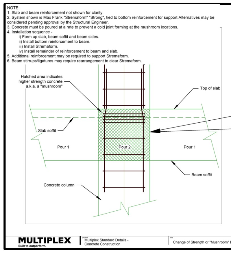
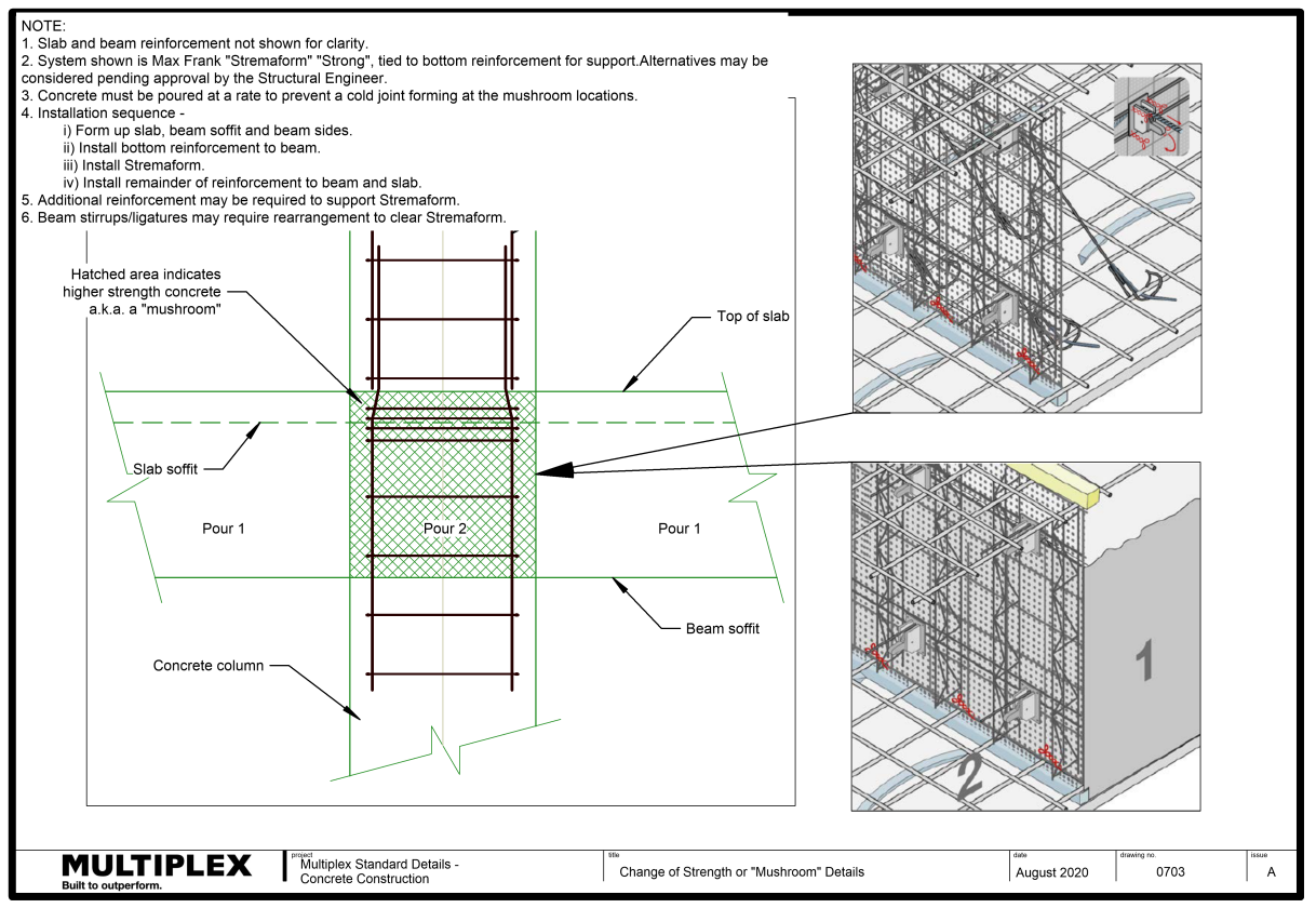
- Multiple concrete strengths (i.e. mushrooming columns)
- Significant height difference (i.e. large folds)
- Use of aliphatic alcohol
- Deep edge beams
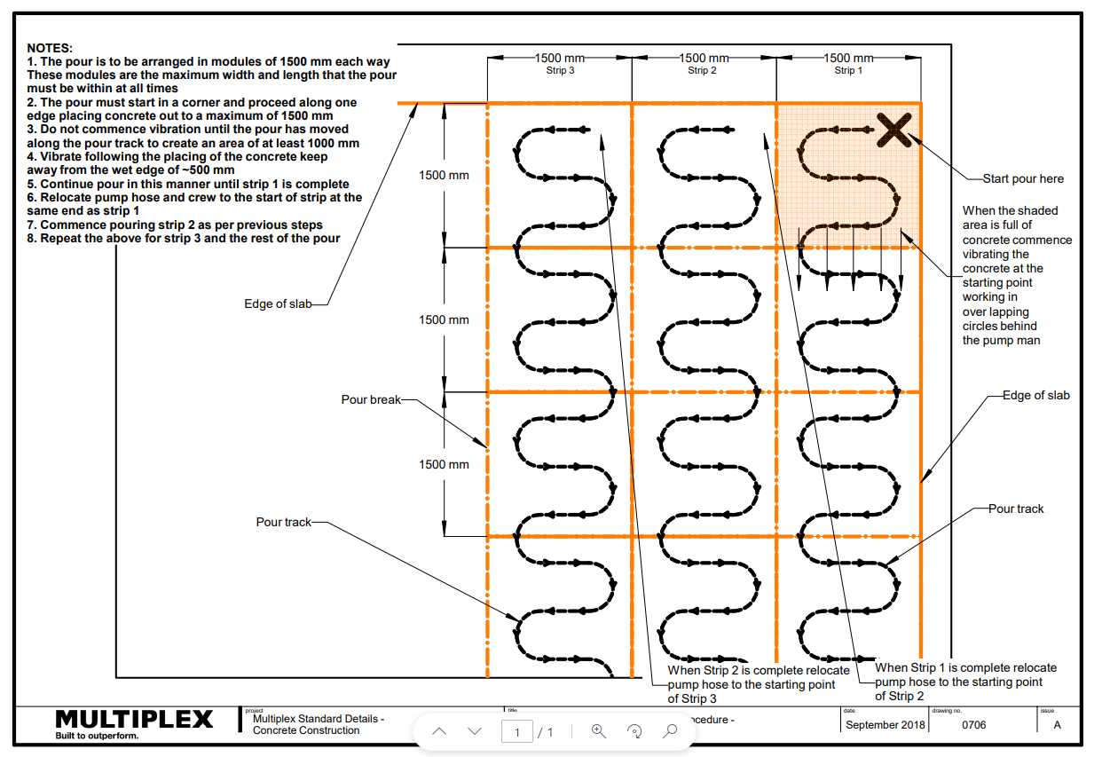
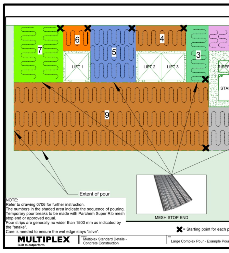
A a pour plan (snake sequence) must be documented and include details as outlined in the Figure 1.
Pour Cycles and Programming
Formwork - Design
Desk Sequencing - where are the priorities?
Preparation
Formwork
What is formwork?
Formwork is the temporary structure into which concrete is poured to create the shape of the structure. The formwork system needs to be strong enough to withstand the loads being placed upon it. These include the dead load of concrete once it has gone off, but also the dynamic live loads such as the wet concrete during pouring, the placement of reinforcement bundles and post tensioning cables.
Formwork must be:
- Signed off by an engineer and a formwork certificate obtained ensuring:
- Any restrictions imposed on the rate of placement is understood (allowance for the hydrostatic pressure).
- Cleaned prior pour.
- Have fillets and drip groves installed.
- Only be removed once the concrete, post tensioning and reinforcement structure can support itself and a structural engineer has given sign off to commence stripping.
- Installed In accordance with 'Formwork' outlined in the Health and Safety Handbook
What is Formwork?
Loads on Formwork
Formwork – Understanding the different Systems
Loads on Formwork
Formwork – Sequencing
Reinforcement
Reinforcement must:
- Have a minimum cover of 30mm on top, bottom and sides or as specified
- Not have an excessive cover
- Use a sufficient number of bar chairs
- Have bars sufficiently lapped
- Have dowel joints fixed in position
- Be placed on plastic bar chairs in exposed areas (i.e. balcony soffits).
Note: Ensure that the first layers of non-stressed reinforcement are in place prior to the installation of tendons.
Why do we use Reinforcement
Reinforcement – Engineer Inspections
Post-Tensioning
What is post tensioning?
Post-tensioning is a method of reinforcing (strengthening) concrete or other materials with high-strength steel strands or bars, typically referred to as tendons.
Post tensioning is a technique for reinforcing concrete. Post-tensioning tendons, which are prestressing steel cables inside ducts or sleeves, are positioned in the forms before the concrete is placed. Afterwards (and once the concrete has gained strength but before the service loads are applied) the cables are pulled tight, or tensioned, and anchored against the outer edges of the concrete.
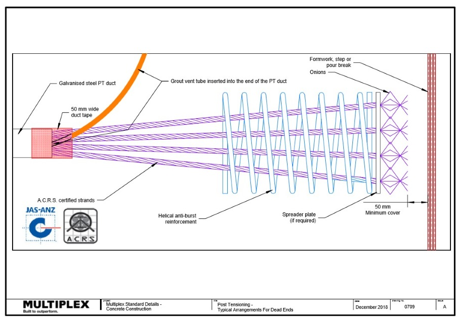
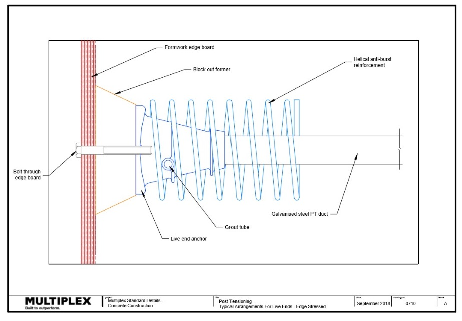
Post tension tendons are ducts or sleeves containing steel cables. They are positioned in a profile wave to strengthen areas of the concrete that are in tension. The cable strands run from their ‘onion’ or dead end, through the tendon ducts and through the live end to an anchor block attached to an edge board or to a pan cast into the concrete. The live end is where the jack is attached for the stressing to occur.

Click on the image for an enlarged version
Advantages of using Post Tensioning
General
Post Tensioning must be:
- Installed In accordance with 'Post Tensioning' outlined in the Health and Safety Handbook.
Duct Chairs
Duct chairs must be:
- Stapled to plywood or
- Screwed to the bond deck.
Post Tensioning and Stressing
Post Tensioning - The Process Brief
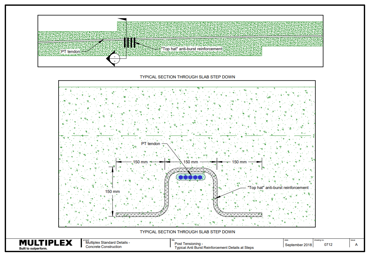
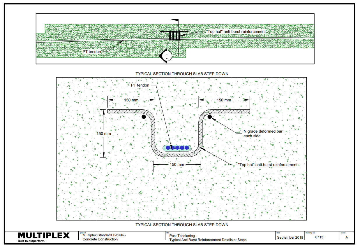
Anti-Burst
Steel reinforcement known as anti-burst is used in the anchorage zone to control cracking caused by tensile forces as a result of the tensioning.
Anti-Burst must be:
- Installed by the PT contractor.
- Tied as per drawings.
- Correctly placed at the anchorage point.
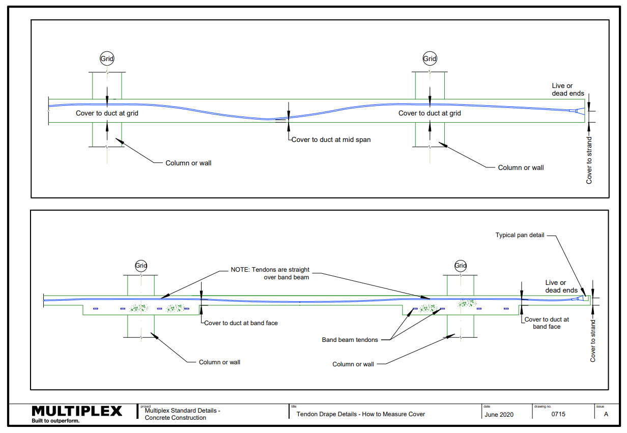
Tendon Ducts
Profiling refers to the positioning of the cables and ducts (also known as tendons).
Tendon ducts must:
- Be installed to correct profile (line and level) within specified tolerances (5mm tolerance for straightness)
- Be tied and supported so that they do not move during concreting.
- Have minimum of 50mm cover to the stressing onion.
Anchorages
Anchorages are used to fix the ends of the tendons in post-tensioning systems. Various designs are available, depending on the system supplier, but basically they are steel blocks through which single or multiple strands pass and are anchored by wedges. The strands may be tensioned individually or as a group.
The anchorages are cast into the concrete and transfer the entire load from the strands into the concrete.
Anchorages must be securely tied at all locations

Click on the image for an enlarged version

Click on the image for an enlarged version

Click on the image for an enlarged version
Services Conduits
Limit the concentrations of service conduits especially at live or dead end.
Initial Stress and Final Stress
The post tensioning is completed in two stages - initial stress and final stress.
The initial stress is usually done the day after the pour and is determined by the concrete reaching a desired MPA strength. These results are provided by the concrete supplier, by conducting a crush test. The tendons are pulled with a hydraulic driven ram that stretches the cable. The stress loads at this point are generally done to alleviate surface cracking.
Following the initial stress, pans get painted at the wedges against the live end block. This is to record the extensions, once the final stress is carried out. The final stress is done in exactly the same way but the amount of tension that the ram creates is detailed for the final loads required for the completed building.
Initial Concrete Strength
- Check that the concrete compression tests have attained the specified compressive strength.
- Never commence initial or final stressing if the concrete has not reached the required compressive strength without specific written approval from the design engineer.
Cutting Strands and Sealing
Cutting refers to cutting the excess stressing strands off in order for these to be patched. This activity can only be done once the tendons are stressed and the cable extensions (the distance the cable has been stretched between the initial and final stress), are measured and recorded.
Sealing refers to the process of using a compound to patch the anchor recess at the slab edge. This is done to stop grout from leaking out when grout tendons are grouted.
- Obtain approval from post-tensioning engineer prior to cutting off excess tendons.
- Check the project specifications for cover requirements and sealing products prior to cutting the strands. If not specified, then a minimum cover of 25mm is to be achieved between the cut strand and the outer face of the filled pocket.
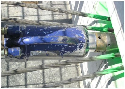
Stressing Jacks
- Ensure calibration certificates are checked every 6 months.
- Confirm jack number on certificate matches jack onsite.
Cutting, Grouting and Sealing
Grouting
Grouting is done to lock the stressed tendons in the duct. The grouting is done by pumping grout into one end of the tendon through a grout tube installed prior to pouring. Each tendon has a grout tube at both ends. One is the inlet tube and the other is the indicator tube so that when grout flows through it, it indicates that it is completely full.
The grouting of the ducts surrounding post-tensioning tendons provides the necessary mechanical connection to transfer the stresses between the tendons and the concrete and also protects the tendons from corrosion.
Grouting using premixed bags must:
- Be injected at the completion of stressing so that the tendons are permanently bonded into the slab system.
- Have grout tubes filled and tied/taped.
- Be recorded in the form of a marked up plan confirming grouting has been completed.
- Have a minimum of six cubes per batch/pallet tested.
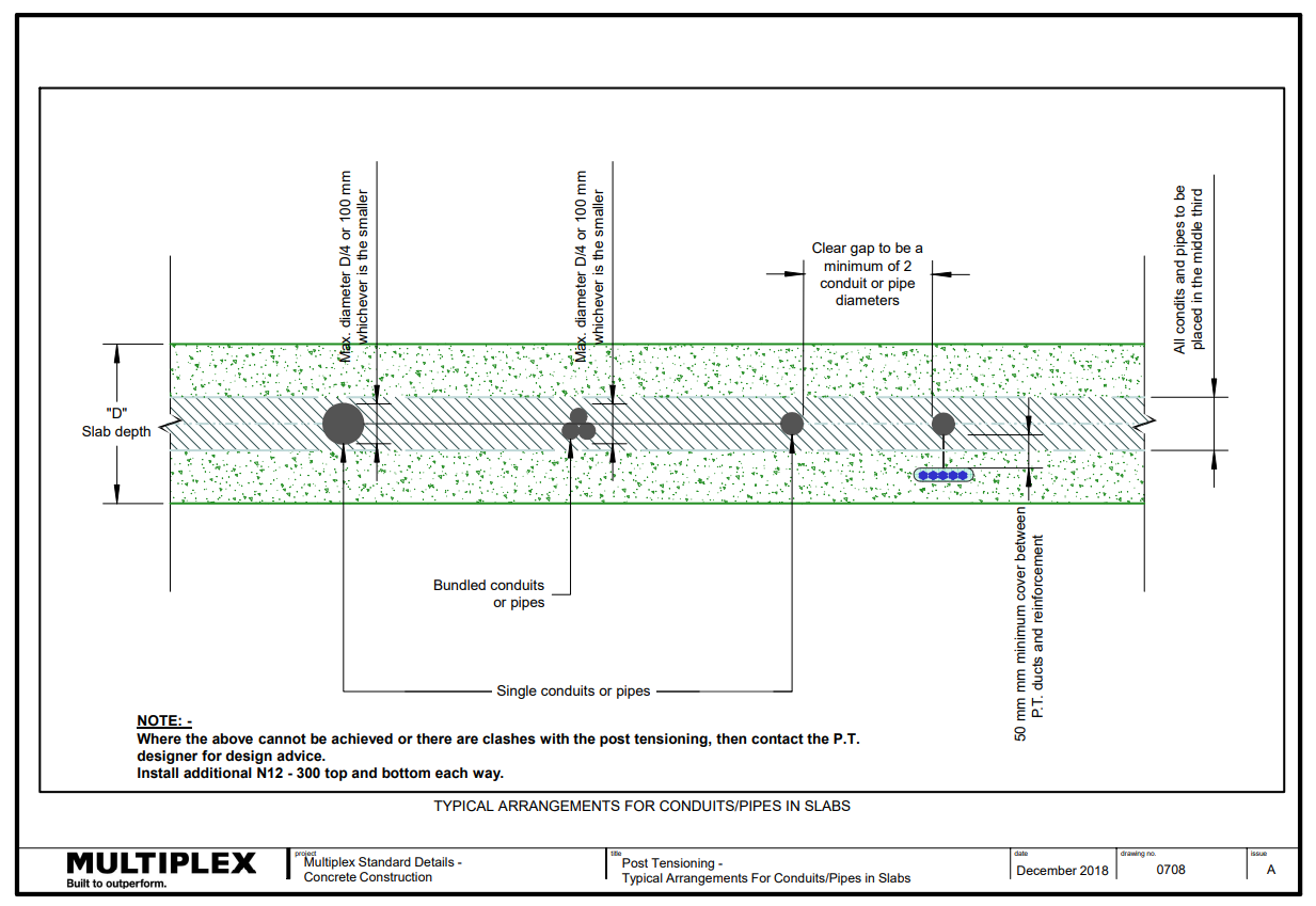
Cast in Services
Ensure conduits, pipes etc. are:
- Placed in accordance with the approved coordinated drawing
- Placed within the slab in the middle third and between the layers of reinforcement
- Held securely in place with bar chairs, tie wire or similar
- Never attached to P.T. ducts
- Spaced to allow complete encasement, but never less than 25mm apart, (single pairs of conduits < 32mm diameter are acceptable with engineer’s approval)
- Spread out as much as possible across the deck or beams
- Wrapped (if a pipe) with a compressible material to nominal 6mm
Pipework with joints must not be cast in.
Note: PE-X piping must be encased in a conduit.
Refer to the Services sections for additional information.
Preparation
Concrete Mix
- Do not add water at the site.
- Ensure the concrete delivered is the approved design mix for the member cast onsite.
- Ensure manufacturer's specifications and the consultant's specification are followed for concrete admixtures.
Placement
Concrete placement must:
- Be placed in accordance with 'Concrete Placement' section of the Health and Safety Handbook
- Follow the pour plan diagram (snake sequence).
- Ensure cold joint locations are as per engineer's details
Note: When placing vertically, never let the concrete fall more than one-and-a-half metres.
Concrete Mix Design
Critical Design Elements – Joints in Concrete during Design Phase
Critical Design Elements – Joints in Concrete
Critical Design Elements – Falls
Compaction
Compaction involves the shaking or vibrating of the concrete to expel any trapped air. This allows the concrete to settle and fills all the space in the forms. But it also enables to concrete to bond and seal to the reinforcement.
Notes:
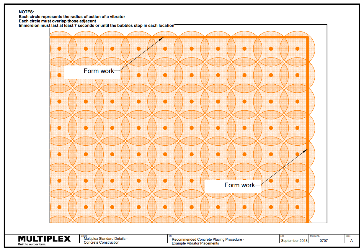
- One 50mm vibrator will compact about 10m3/hr. and has a radius of influence of ~250mm.
- Ensure you overlap the radius of influence so that concrete is thoroughly compacted
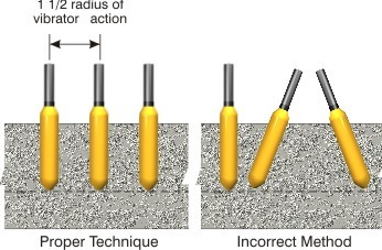
- The radius of action vertically is 1.5 x the vibrator insertion.
- If your proposed pour rate is 20-30m3/hr you will require two to three vibrators.
During concrete compaction ensure:
- That the reinforcement, tendons, inserts and fixings are completely surrounded by dense concrete.
- At least one spare vibrator is available during every pour.
- Vibrator is inserted quickly for 7 seconds or until bubbles stop and then withdrawn slowly for each location.
- Vibrator is not used to spread concrete.
- Vibrator does not touch either the reinforcement or the formwork.
Curing
Curing is important as it ensures that the bond between the paste and the aggregate gets stronger. Concrete will not harden properly if it is left to dry out too quickly. Concrete that is cured is less likely to crack, is stronger and more durable.
Curing must:
- Commence immediately after finishing (horizontal and vertical elements).
- Be applied at the correct rate.
Finishes
Finishing comprises the screeding, floating or trowelling of the concrete surface to densify and further compact the surface layer of concrete, as well as providing the finish or look required.
- Confirm concrete is finished to the approved finish with the particular attention paid to areas requiring slip/skid resistance.
- If slip/skid resistance is nominated, prepare a sample before work commences and independently test the sample to confirm that it meets the slip resistance required.
Concrete Curing
Critical Design Elements – Concrete Finish
Back Propping
With the correct design and sequence undertaken, it is important to understand back propping. Back propping is used to support a suspended slab while the formwork is being stripped (removal of all the false work and formwork). It is a system of structural members used to temporarily support loads during construction. Back propping remains in place until the slab gains enough strength to support itself and the load above it. Back propping is a vitally important part of building safe, economic and quality concrete structures.
Critical issues to consider include:
- Design drawings showing setout, size and type of props
- Prior to removing any back propping the concrete slabs must have the structural engineer's approval that the desired strength (MPA) has been achieved
- Post tensioning must be finally stressed and grouted
- The system for stripping has been approved and signed off by the design engineer prior to commencing any removal of back propping.
Concrete Testing
What is a slump test?
Before a truck load of concrete is discharged into the concrete pump it is necessary to ensure that concrete is tested to the prescribed workability and strength levels as detailed in the specification.
When trucks arrive to deliver concrete, concrete from each truck will be tested on site prior to pour.
The test performed before concrete is poured is called a slump test. The test measures the physical ‘slump’ of the concrete mix as it comes out of a conical shaped mould. The measured slump must be within a set range, or tolerance, from the specified slump.
Concrete Testing Thermocouples
What are the various slumps?
Typically, admixtures are incorporated into concrete design to assist with the plastic concrete consistency for uses such as:
- Dry slump concretes (20 to 50mm) giving very low shrinkages due to reduced water content, but are difficult to work in their plastic state.
- Normal slump concretes (60 to 100mm) giving suitable workability for general purpose applications.
- Medium slump concrete (120mm to 160mm slump) for improved pumpability (130 plus metres high)
- Flowing concrete (180mm plus slump) for ease of placement and good off-form finish
What is a compression (strength) test?
The compression test shows the best possible strength concrete can reach in ideal conditions. The compression test measures concrete strength in the hardened state. The testing is done in a laboratory off-site. The only work done on site is to make a concrete cylinder for the test. The strength is measured in Megapascals (MPa) and is commonly specified as a characteristic strength of concrete measured at 28 days after mixing. The compression strength is a measure of the concrete’s ability to resist loads which tend to crush it.
Slump Test
- Ensure slump tests are conducted as per specification
- Ensure sample is taken from the early part of the load. Never take the sample from the first concrete out of the mixer. Let out at least 0.2 of a cubic metre before taking a test sample
- Reject any concrete that exceeds designed slump (+ or – 15mm)

Click on the image for an enlarged version
Slump Test
Spread/Flow Test
- Ensure spread/flow test is conducted for self compacting concrete
Strength Test
- Minimum 1 sample (3 cylinders) per 50m3 for slabs, footings & columns
- Minimum 1 sample (3 cylinders) per 25m3 for walls
- Ensure cylinders are stored correctly:
- Protected from wind
- In a moist condition
- Sheltered from sun
- Protected from extremes in temperature.
Slump Flow Test