Bathrooms
Key Considerations
- Material selection
- Preparation
- Installation and application
- Testing
Elements in waterproofing systems include:
- Waterproofing membrane
- Bond breakers and de-bond zones
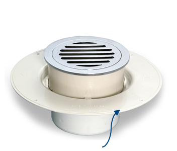
- Floor Wastes
- Sealant for penetrations
- Waterstops and hobs
- Drainage outlets and leak control flanges
- Substrates (floor and wall)
- Falls in substrate and finishes
Design
Internal bathroom design must consider:
- Internal wet area waterproofing shall be generally be in accordance with AS 3740
- Standard MPX 17100 series of drawings.
- Substrates which incorporate a fall to the floor waste.
- Set down of not less than 50 mm (where feasible) and be oversized by up to 20mm each side to allow framing and sheeting to be inside of the set down.
- PT stressing pans and construction joints being avoided.
- Fibre cement sheet linings in all internal shower recesses
Membranes for bathrooms must be:
- Class 3
- Tested to AS4858
- In accordance with the membrane selection chart (to be read in conjunction with the membrane Locations chart)
Preparation
Concrete Placement
During concrete placement, ensure that:
- Falls to wastes are as per concrete outline plans
- Falls are diverted away from doors, service penetrations, upstands etc.
- Set downs are formed correctly (Preferably 50mm below outside finish floor level / water stop angle)
- Leak control flanges:
- Are cast in
- Are finished level with the concrete surfaces or slightly below
- Have provision for drainage at the structural level.
Concrete Preparation
- Concrete substrates must:
- Have a smooth finish
- Be prepared as specified by the membrane manufacturer.
- Confirm moisture content of substrate meets the requirement of the membrane manufacturer.
- Curing compound must not prevent adhesion of the selected membrane. Concrete may require additional preparation, e.g. grinding, shotblasting, etc., to remove contaminants.
- Prepare the concrete to remove:
- Form release agents
- High spots and sharp protrusions
- Loose or friable concrete
- Offsets
- Tie holes
- Blow holes greater than or equal to 2mm.
- Cracks greater than 1mm or as specified by the membrane manufacturer, must be routed out and filled flush with a sealant if specified.
- Where retrofitted flanges need to be installed they are to be finished level with or slightly below the concrete surface (cutting out or grinding of finished concrete as required), never higher.
Wall Sheeting
Before applying the membrane to wall sheeting:
- Fix studs correctly to ensure wall sheets are structurally sound as per manufacturer's installation guidelines.
- 6mm FC sheeting screw spacing is determine by tile weight as per manufacture installation guidelines
- Moisture Resistance (MR) Plasterboard sheeting screw spacing is determine by tile weight as per manufactures installation guidelines
- Set joints flush, minimum of 2 coats of wet area base coat and paper tape.
- Prepare internal and external corners ready for membrane as per manufacturer’s instruction.
- Cut circular penetrations with a hole saw (5mm annular gap).
- Bell out/chamfer penetrations.
- Apply approved sealant around plumbing and wall sheeting to seal annular gaps (e.g. shower head spouts, tap bodies, PVC waste pipes).
- Fill bottom of sheeting gaps as appropriate.

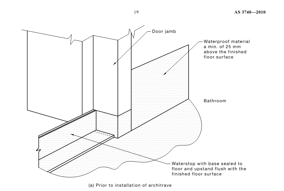
Click on the image to view an enlarged version

Click on the image to view an enlarged version
Water Stops
What is a water stop?
A water stop is an aluminium angle used to create a vertical extension of the waterproofing system, forming a barrier to prevent the passage of moisture out of the shower recess and the wet area.
Water stops must:
- Finish above or at the finished floor level (FFL), not below tiles
- Be fitted tight and hard back to the stop bead at doorways
- Be fixed to the slab with epoxy or mechanical fixing
- Have the gap underneath filled with drypack sand/cement
- Be installed at doorways and showers
Refer to MPX Guide to Waterproofing for further information and detailing for water stop angles.
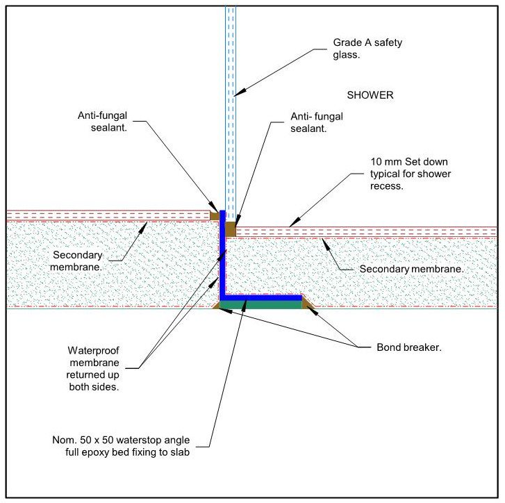
Bond Breakers
What are bond breakers?
A bond breaker, as stated in Australian Standard 3740 is a “system that prevents the membrane bonding to the substrate, bedding or lining”
Why is Bond Breaker required?
Bond-breakers allow movement of membranes to cater for differential movements. This will occur at the junction of different materials, and most notably, the:
- Junction of concrete floor and walls
- Vertical internal corners of walls
- Transition from concrete to plastic i.e. cast in leak control flange
- Transition from concrete to aluminium at waterstop angles
- Ends of the waterstop angles and the door frame
- Cracks in concrete substrate
The bond-breaker material increases the area over which the membrane can elongate.
The bond-breaker material must not adversely affect the performance of the membrane.
Bond breakers must be:
- Applied in accordance with manufacturer’s recommendations
- Fully cured before membrane is applied over. Check manufacturers guidelines for curing duration
- Compatible with membrane.
Application
Priming
Primers must be:
- Applied as per manufacturer’s guideline
- Covered within the nominated time frame
- Applied with the required moisture content
- Compatible with substrates, including leak control flange and other components
- Only applied when the air temperature is higher than 5 degrees or as specified by the manufacturer.
Membrane
Membranes must be:
- As per the approved sample
- Applied as per manufacturer’s instructions taking account of the factors that might impact the membrane performance (e.g. moisture content of the concrete, relative humidity, temperature).
- Not applied when temperate is lower than 5 degrees (refer to manufacturer’s guidelines).
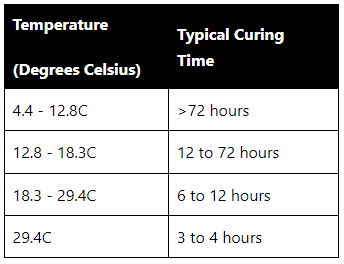
- Applied with consideration to the curing time where temperatures are lower than 10 degrees or higher than 30 degrees.
- Completely dry before curing can commence and flood testing or toppings are applied.
Notes:
- Failure to observe this requirement can lead to membrane re-emulsification that requires expensive remedial work.
- There is a fundamental difference between a touch dry membrane and a cured membrane.
- When preparing programs, this time frame must be allowed for.
- Weather and other environmental factors will influence the time it takes for drying and curing.
- Cold and wet = long time to dry and cure.
- Hot and dry = fast drying and curing.
- Enclosed perimeter with little to no cross ventilation = slow drying and curing.
Table 1: An example of temperatures and time for curing but refer to manufacture requirements.
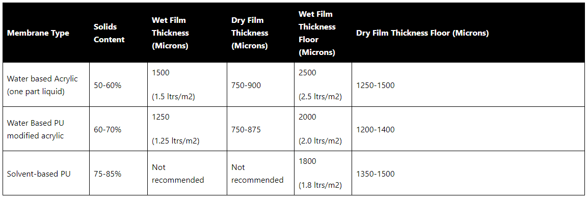
Film Thickness
- All membranes, rely upon the final film thickness to be able to function as designed. The correct thickness ensures the mechanical properties will be preserved and the membrane will be durable and perform the desired function.
- Liquid membranes must:
- Be tested with a comb during application to determine the wet film thickness as per Figure (Note: A membrane with 50% solids applied at a thickness of 2mm out of the can will dry out to 1 mm DFT).
- Be tested using an ultrasound device for cured acrylic and polyurethane membranes to determine the dry film thickness and destructive testing for cured cementitious membranes with a minimum of one-test conducted and an additional test conducted for each 10m2 chosen at random.
- Have records of wet and dry film thickness values recorded in the Sub-contractors Checklists.
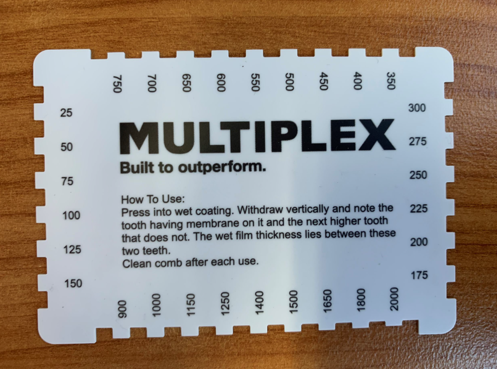
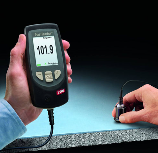
Table 2: Example only of membrane thickness for water based and solvent based PU
Flood Testing
- Flood testing for a minimum of 24 hours should be undertaken at the following frequency:
- Minimum 20% of each type of wet area (i.e. bathroom, laundry) but the recommendation is 100%
- 100% for shower areas
- Measure the water level at the beginning and end of the flood test
- Carry out visual inspection of all adjoining areas for evidence of leakage.
Protection
- Membranes must be fully cured before accepting light traffic, regardless of program pressures.
- Adequate protection (i.e. corflute) must be put in place by the subcontractor to ensure exposed membranes are protected from damage.
- Signage to be clearly posted
- Physical barriers to be installed to prevent other trades entering areas where membranes are curing or unprotected.
Quality Video
Waterproofing a Shower Recess (NSW only)
Video Bookmarks: You can directly go to the specific chapter by following the below listed time stamps.
Introduction and cost of waterproofing defects: 0 sec
Components of shower recess waterproofing: 1 min 32 sec
Concrete Placement: 2 min 37 sec
Cast in Leak Control Flange: 3 min 25 sec
Concrete Preparation: 3 min 51 sec
Wall Substrate: 5 min 3 sec
Water Stop Angles: 6 min 9 sec
Bond Breaker: 6 min 38 sec
Primer: 7 min 30 sec
Membrane: 8 min 7 sec
Screed: 11 min 14 sec
Secondary Membrane: 12 min 27 sec
Key Takeaways: 12 min 54 sec
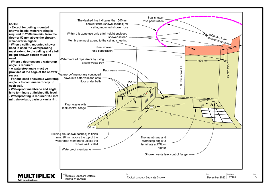
Multiplex Standard Details
17101 - Typical Layout - Separate Shower
17102 - Typical Layout - Shower Over Bath
17104 - Metal Door Frame Details
17105 - Metal Door Frame Details - Section
17106 - Cavity Door Details – Plan View
17107 - Cavity Door Details – Section Through Threshold
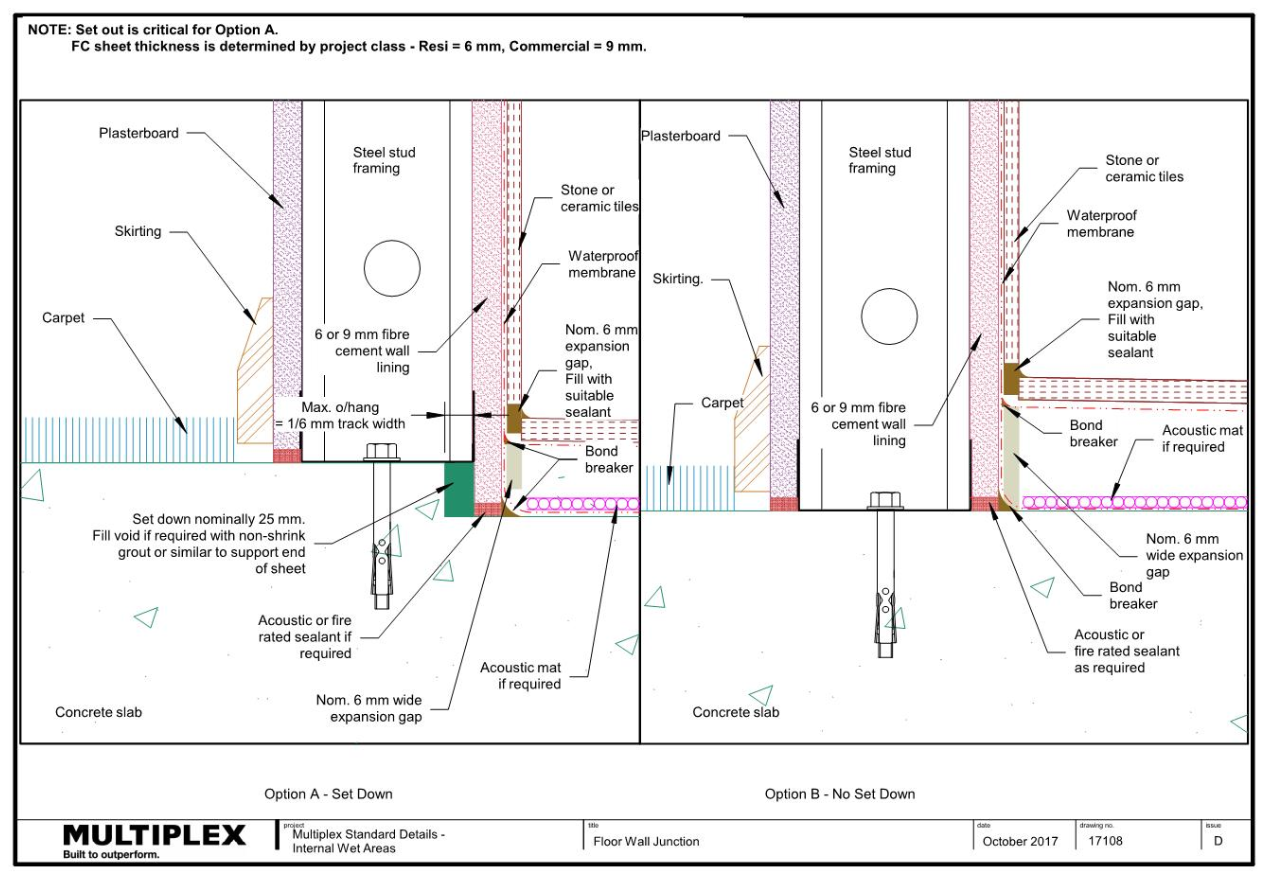
17108 - Floor Wall Junction
17109 - Floor Wall Junction
17111 - Bath Tub Installation, Insert Bath Detail & Bath Front
17112 - Insert Bath Wall Detail
17113 - Bath Tub Installation Details - Plastic Inset Bath - No Shower Over
17114 - Bath Tub Installation Details - Plastic Inset Bath - With Shower Over
17115 - Bath Tub Installation Details - Plastic Rimmed Bath - With Shower Over
17117 - Bath Tub Installation Details - Free Standing Bath - With Shower Over
17118 - Bath Tub Installation Details - Detail 1 From 17113
17119 - Bath Tub Installation Details - Detail 2 From 17113
17120 - Bath Tub Installation Details - Detail 3 From 17113
17121 - Bath Tub Installation Details - Detail 4 From 17113
17122 - Bath Tub Installation Details - Detail 5 From 17114
17123 - Bath Tub Installation Details - Detail 6 From 17114
17124 - Bath Tub Installation Details - Detail 7 From 17115
17125 - Bath Tub Installation Details - Detail 8 From 17115
17126 - Bath Tub Installation Details - Detail 9 From 17115
17127 - Bath Tub Installation Details - Detail 10 From 17115
17128 - Bath Tub Installation Details - Elevation of Bath Side Showing Vents
17135 - Typical Vertical Corner Detail - Tiled 135 degrees Corner
17136 - Typical Vertical Corner Details
17137 - Mixer Tap Details
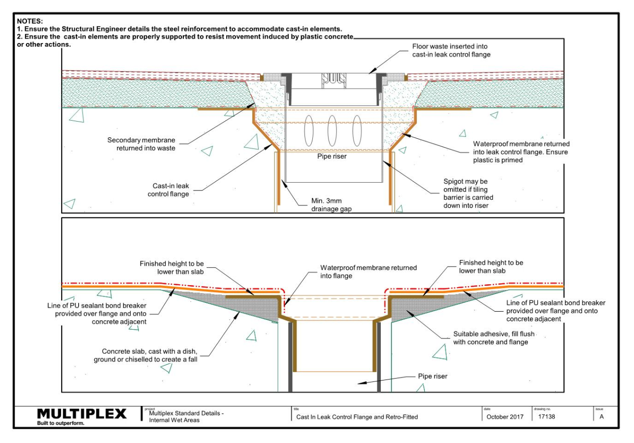
17138 - Cast In Leak Control Flange and Retro-Fitted
17140 - Shower Screens - Floor Details
17141 - Shower Screens - Wall Abutments
17142 - Shower Wall Angle Detail - Elevation of Floor Angle
17143 - Shower Wall Angle Detail - Section Through Floor Angle
Document Control
Version 3.1 December 2020
Major Update: The following drawings have been added to the Multiplex Standard Details for Bathrooms Waterproofing:
17135, 17141