Concrete Masonry
Key Considerations
- Penetration details incl. bond beams
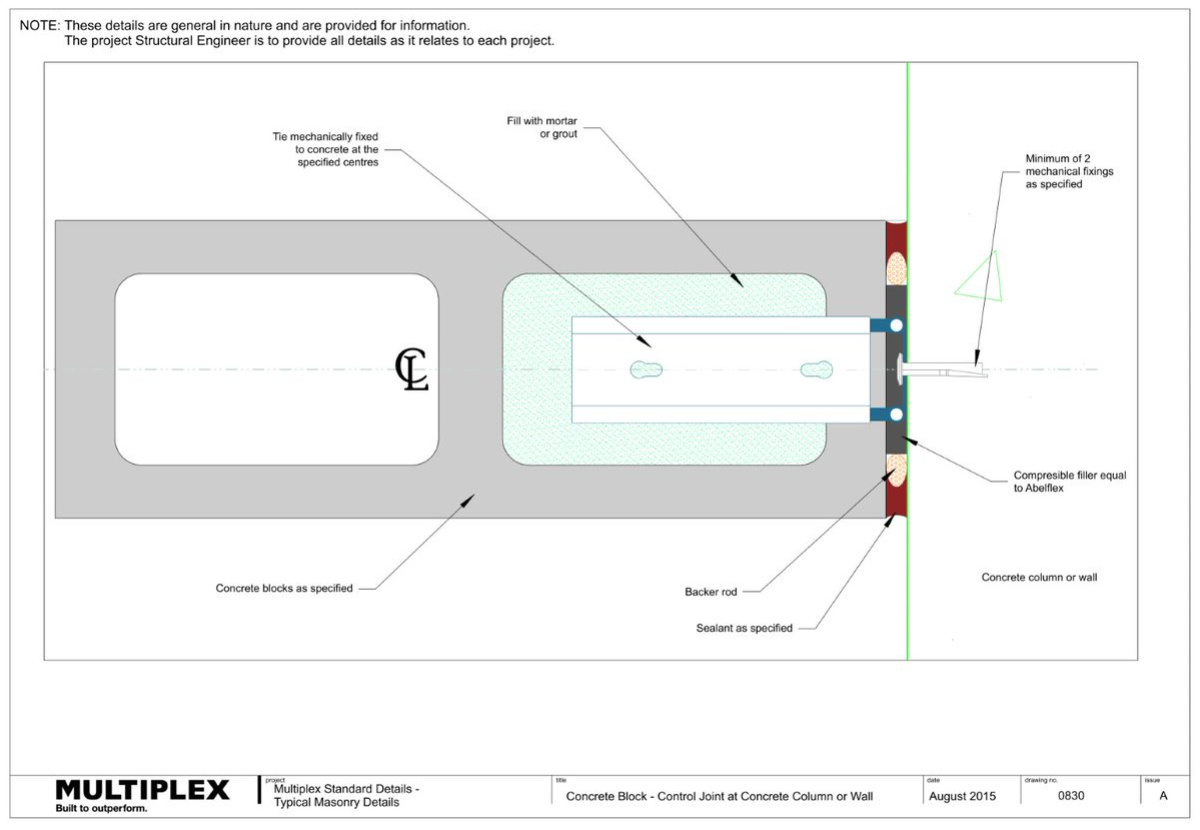
- Location of control joints
- Grout filling
- Reinforcement and stiffeners
- Dimensions and fire properties of the block material
What is concrete masonry?
- Concrete masonry is a generic term covering many building systems that incorporate bricks and blocks of many different shapes and sizes, colours and textures, strengths and other mechanical properties.
- Concrete masonry units, for use in walls, fall into two broad categories – concrete bricks and hollow concrete blocks.
- Concrete masonry can be reinforced or unreinforced.
- Reinforced concrete masonry provides efficient resistance to wind loads and earthquake loads in large panels in low-rise commercial and industrial buildings.
- Unreinforced concrete masonry is widely used in high-rise and medium-rise commercial and residential buildings with loadbearing and non-loadbearing fire-rated walls.
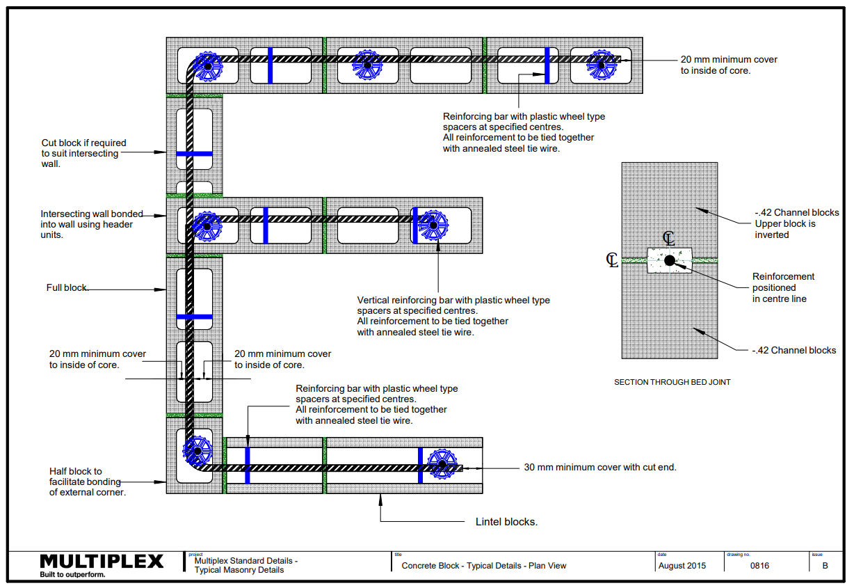
Concrete blockwork consists of all elements outlined in the Figure.
Why use concrete masonry walls?
They provide:
- Durable walls suitable for multiple locations
- Thermal resistance performance, low energy costs, low environmental impact and effective sound transmission barriers between external and internal environments of the buildings.
Selection
Samples and prototypes in addition to those outlined in the specification must be submitted/built as per link below.
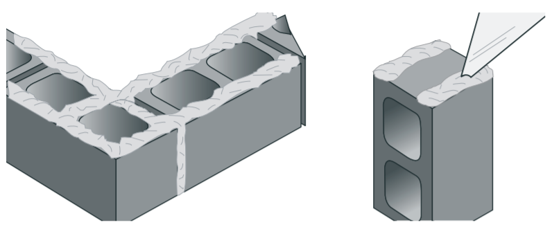
Mortar Joints
Mortar joints are to be in accordance with ‘Mortar Joints’ under Clay Masonry.
- Blocks must be:
- Laid with two strips of mortar up to the vertical (or perpend) joints.
- Blocks are laid with face shell bedded.
Restraint Fixings
What is a head restraint?
Head restraints provide simple support to the top of a masonry panel by transferring lateral load (usually wind or internal pressure load) from the masonry to the primary structure, whilst allowing some vertical deflection (movement) in the frame in relation to the top of the wall.
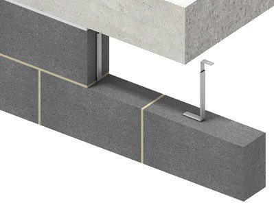
Head restraints must be:
- Positioned centrally in the width of the wall, where this is not possible the centre of the stem should be at least 50mm from the edge of the wall.
- Positioned at 450mm or 900mm centres depending on the expected load at the top of the wall.
- Fixed with M8 bolts or as specified by the manufacturer.
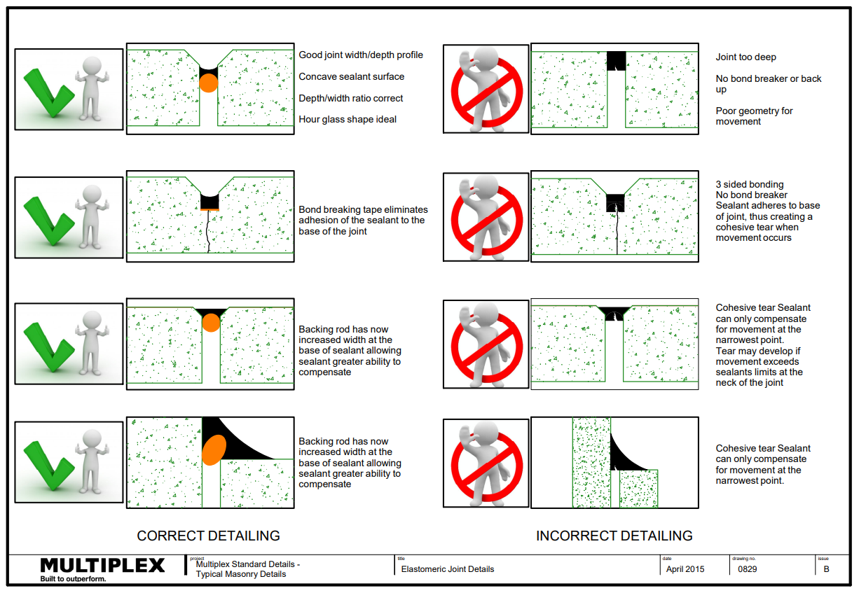
Expansion Joints
What are expansion joints?
Expansion joints are:
- Typically used to accommodate thermal and moisture expansion in masonry.
- A continuous vertical or horizontal joint, left completely free of mortar and filled with elastomeric sealant to keep it watertight.
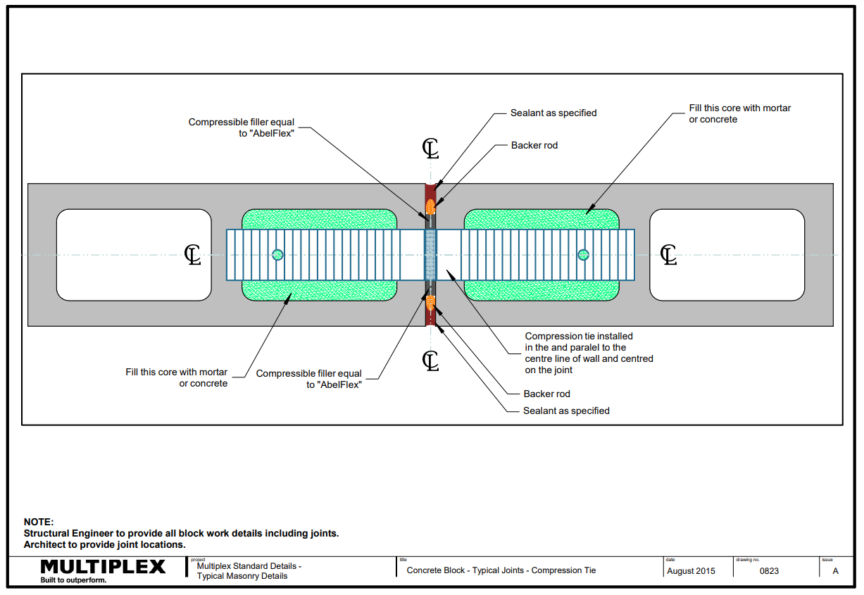
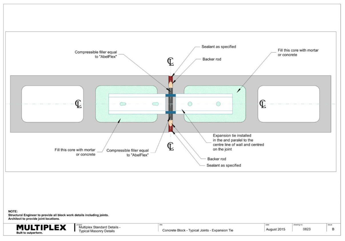
Expansion joints must be:
- Located strictly as detailed in both the Architectural and Structural drawings.
- Cleaned, and include a compressible filler (e.g. “Abelflex”)
- Located:
- Where the height of a wall changes by more than 20% of its lesser height.
- Where walls change thickness.
- At movement joints in the structure.
- At a distance from all corners not greater than 4500mm and as close to the corner as practical.
- At junctions of walls constructed of different masonry or other materials
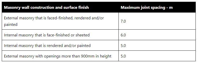
- In accordance with AS3700 Table 4.2 outlined below:
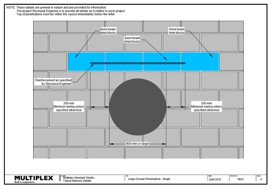
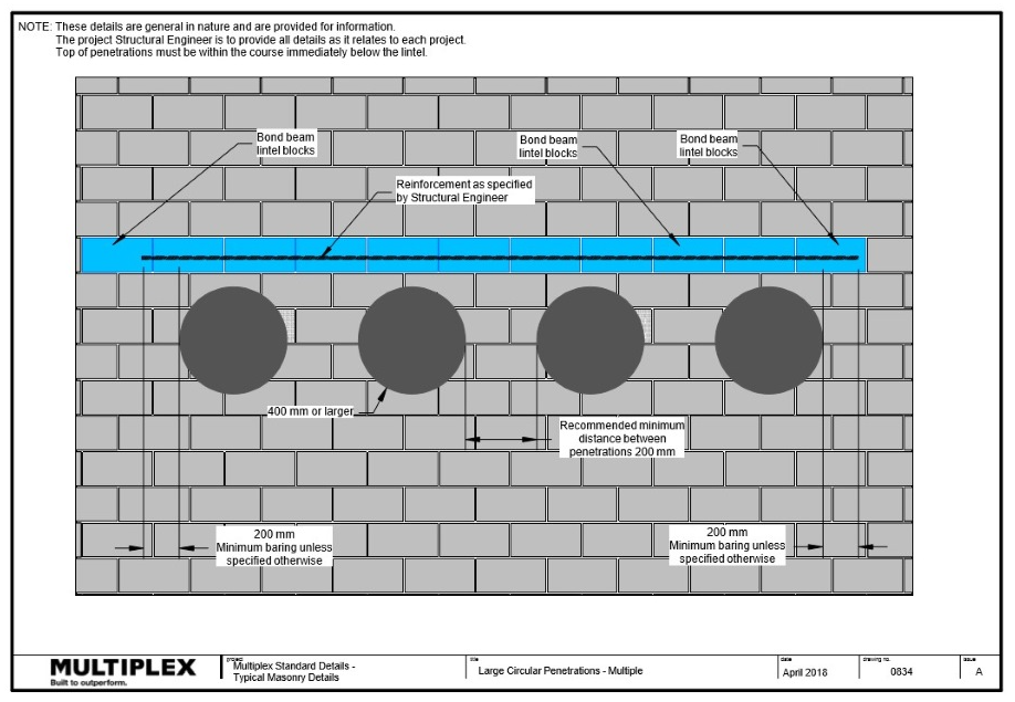
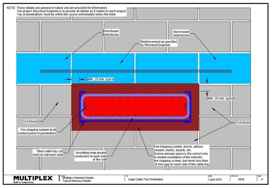
Bound Beam Lintels
What are bond beam lintels?
Bond beam lintels are used to support masonry over openings such as doors and windows.
Bond beam lintels must be:
- Installed in accordance with the structural engineer details.
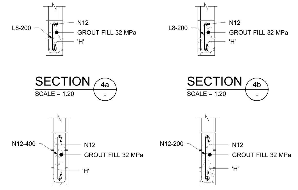
- Generally, as per the details outlined in the Figures below.
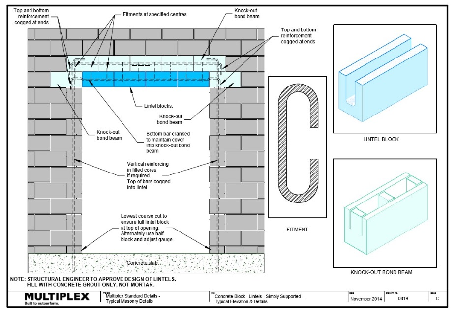
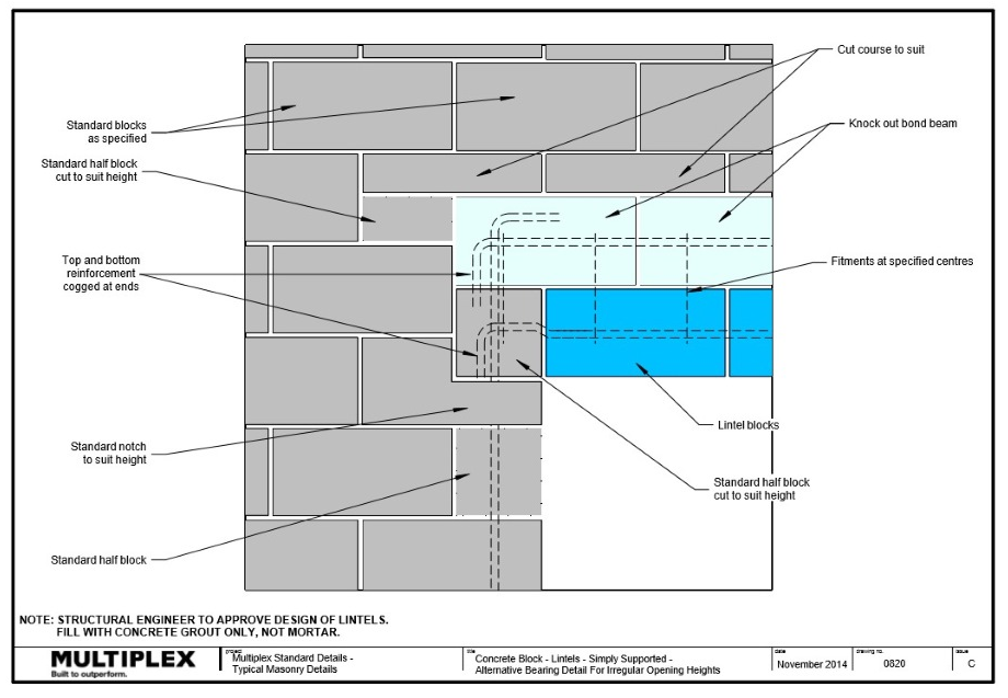
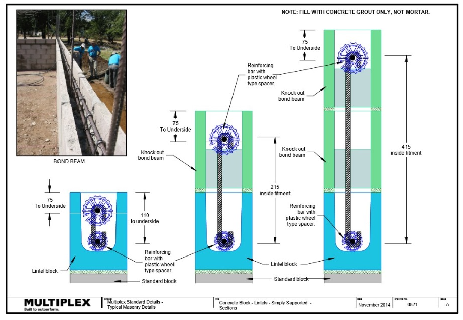
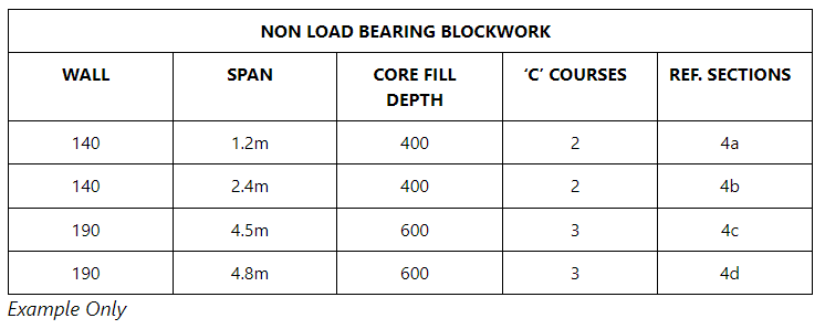
See below example showing the various blockwork details for different lintel spans
Wall Stiffeners and Reinforcement
What are wall stiffeners?
Wall stiffeners are provided when a wall exceeds a certain height, above which, the masonry is incapable of self-support.
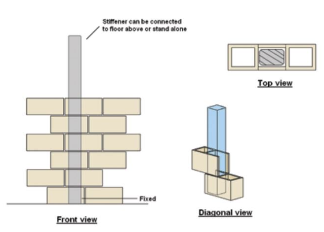
Wall Stiffeners
Wall stiffeners must be installed:
- In accordance with the structural engineer details
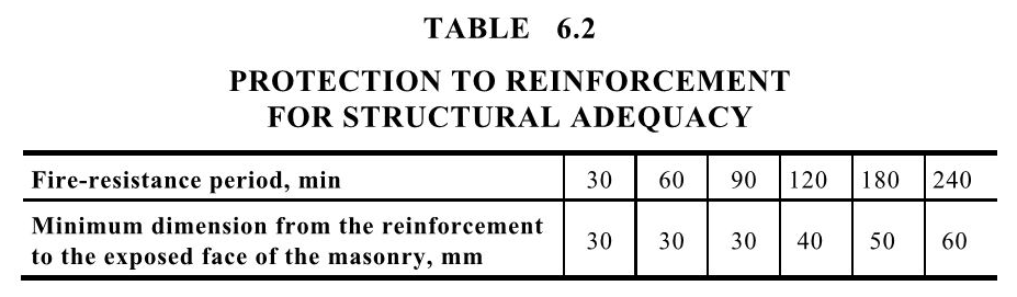
- In block work that has a minimum fire resistance level as specified by Table 6.2 of AS 3700:2018 or established by fire test.
Reinforcement
Reinforcement must be:
- Installed in accordance with the structural engineer details
- In the core with the specified cover and firmly fixed in place to prevent displacement during grouting.
- Overlapped and tied as per engineer's requirements.
Reinforcement must have:
- A minimum of 16mm cover in non-exposed locations measured from the inside of the core
- A minimum of 20mm in exposed locations measured from the inside of the core
Note: Fire resistant blockwork must have the minimum cover as specified by Table 6.2 of AS 3700:2018 or as established by a fire test.
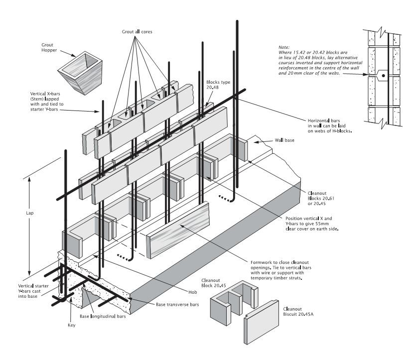
Grout Fill
What is grout?
Grout is highly workable concrete that can be poured or pumped into small spaces, such as the cores of blocks.
Why is grout required?
Where required, concrete grout is an essential element of the construction to ensure reinforcement is encapsulated so that the structure works as designed.
- Before commencing placement of the grout, it is important that the cores should be clean of debris and free of mortar 'dags' projecting into the core.
- In hot weather it may be necessary to hose the cores out with water in order to cool the blocks and so prevent 'flash-setting' of the grout. If so, this hosing should be completed at least 30 minutes before the grout is placed.
- Grout used to fill the cores or blockwork walls must:
- Be approved by the structural engineer.
- Have compressive strength as detailed in the structural engineer's specifications (but never less than 12 MPa).
- Be tested in accordance with the structural engineer's specification or a minimum one test per pour.
- Have the cores completely filled with the reinforcement and surrounded without segregation of the constituents.
- Filled to the top of the blockwork except if it is an intermediate joint, where it should be left 300mm short.
- Filled progressively as per structural engineer's specifications (generally grouting in lifts of no more than 1.2 metres should not be attempted in one pour. Where the lift is more than 1.2 metres, it is preferable to fill the cores in two stages at least 30 minutes apart).
- Be compacted by rodding with a round bar or a vibrator.
- Have a tap test performed to confirm complete filling of the cores.
- Grout may be mixed on site and poured from buckets into hoppers placed on top of the wall. Alternatively, for larger jobs, the grout can be delivered by transit mixer and pumped into the cores, using a small nozzle on the hose.
- Reinforced concrete block walls must have:
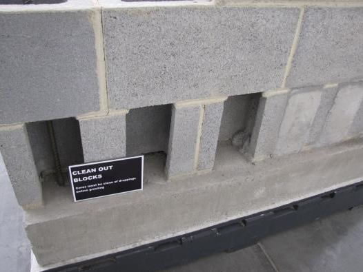
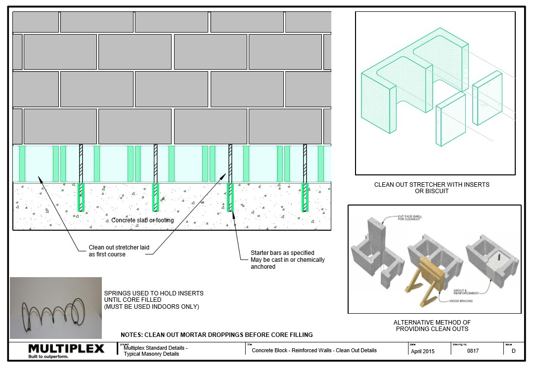
- Cleanout blocks for the first course
- Cores cleaned before core filling
- Cores wetted before grouting.
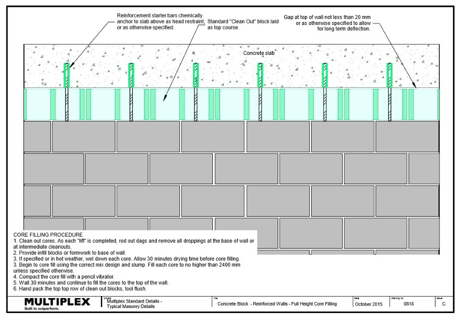
Core Filling Procedure
- Clean out cores. As each lift is completed, rod out dags and remove all droppings at the base of wall or at intermediate cleanouts.
- Provide infill blocks or formwork to base of wall.
- If specified or in hot weather, wet down each core. Allow 30 minutes drying time before core filling.
- Begin to core fill using the correct mix design and slump. Fill each core to no higher than 2400mm unless specified otherwise.
- Compact the core with a pencil vibrator.
- Wait 30 minutes and continue to fill the cores to the top of the wall.
- Hand pack the top row of clean out blocks and tool flush.
Wall Penetrations
Document Control
Version 2.1, April 2021