Internal Plant Rooms
Key Considerations
- Material Selection
- Preparation
- Installation and Application
- Testing
Design
Plant room design must consider:
- Waterproofing to AS 4654
- Standard MPX 17400 series of drawings.
- Falls and drainage outlets arranged to ensure adequate drainage around plinths and other encumbrances
- Floor waste location to be coordinate to plant/plinth
- Drainage outlets cast in and made from cast iron or stainless steel.
- Bunds must be provided around all floor level penetrations
- Water discharge from the plant and equipment must be drained into waterproofed bunds
- Plant must be mounted on plinths
- Plinth location and sizing must never result in trapped water
- Plinth location must never be closer than 100 mm from any other plinth, wall, column, etc.
- Steel framing must be installed on pedestals, minimum 150mm high or above overflows.Conduits cast into slabs or walls spread apart with a minimum of 50 mm between each.
- Conduits that are fully enclosed by posts, columns or the like, cut not less than 100 mm above the top of the concrete.
- Conduits brought out via vertical surfaces and be angled down to ensure water drains away from the wall.
- Door openings to internal spaces incorporating a hob at a minimum 100mm above the FSL.
- Incorporate a ramp and grated drain to door openings where a hob cannot be installed
- Stair thresholds having the concrete ramped upwards to ensure water flows away from the stairs.
- Stair well edges incorporating a kerb minimum 150 mm high.
- Floor wastes suitably arranged to prevent the creation of stresses in the slab that can result in cracking.
Plant room membranes must:
- Tested to AS4654.1 & AS4858 where used externally
- Be in accordance with the membrane selection chart
Preparation
Concrete Preparation
- Concrete substrates must:
- Have falls 1:80 to 1:100 to the stormwater drainage outlet.
- Have a smooth finish
- Be prepared as specified by the membrane manufacturer.
- Confirm moisture content of substrate meets the requirement of the membrane manufacturer.
- Curing compound must not prevent adhesion of the selected membrane. Concrete may require additional preparation, e.g. grinding, shotblasting, etc., to remove contaminants.
- Prepare the concrete to remove:
- Form release agents
- High spots and sharp protrusions
- Loose or friable concrete
- Offsets
- Tie holes
- Blow holes greater than or equal to 2mm.
- Cracks greater than 1mm or as specified by the membrane manufacturer, must be routed out and filled flush with a sealant if specified.
- Where retrofitted flanges need to be installed they are to be finished level with or slightly below the concrete surface (cutting out or grinding of finished concrete as required), never higher.
Bond Breakers
What are bond breakers?
A bond breaker, as stated in Australian Standard 4654 is a “system that prevents the membrane bonding to the substrate, bedding or lining”
Why is Bond Breaker required?
Bond-breakers allow movement of membranes to cater for differential movements. This will occur at the junction of different materials, and most notably, the:
- Junction of concrete floor and walls
- Vertical internal corners of walls
- Transition from concrete to plastic i.e. cast in leak control flange
- Cracks in the substrate
- Transition from concrete to aluminium at waterstop angles
- Ends of the waterstop angles and the door frame.
The bond-breaker material increases the area over which the membrane can elongate.
The bond-breaker material must not adversely affect the performance of the membrane.
Bond breakers must be:
- Applied in accordance with manufacturer’s recommendations
- Fully cured before membrane is applied over
- Compatible with membrane.
Application
Priming
Primers must be:
- Applied as per manufacturer’s guideline
- Covered within the nominated timeframe
- Applied with the required moisture content
- Compatible with substrates, including leak control flange and other components
- Only applied when the air temperature is higher than 5 degrees or as specified by the manufacturer.
Membranes
Membranes must be:
- As per the approved sample
- Applied as per manufacturer’s instructions taking account of the factors that might impact the membrane performance (e.g. moisture content of the concrete, relative humidity, temperature).
- Not applied when temperate is lower than 5 degrees (refer to manufacturer’s guidelines).
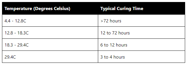
- Applied with consideration to the curing time where temperatures are lower than 10 degrees or higher than 30 degrees.
- Completely dry before curing can commence and flood testing or toppings are applied.
Notes:
- Failure to observe this requirement can lead to membrane re-emulsification that requires expensive remedial work.
- There is a fundamental difference between a touch dry membrane and a cured membrane.
- When preparing programs, this time frame must be allowed for.
- Weather and other environmental factors will influence the time it takes for drying and curing.
- Cold and wet = long time to dry and cure.
- Hot and dry = fast drying and curing.
- Enclosed perimeter with little to no cross ventilation = slow drying and curing.
Table 1: Example temperatures and time for curing
Film Thickness
All membranes, rely upon the final film thickness to be able to function as designed. The correct thickness ensures the mechanical properties will be preserved and the membrane will be durable and perform the desired function.
Liquid membranes must:
- Be tested with a comb during application to determine the wet film thickness as per Figure (Note: A membrane with 50% solids applied at a thickness of 2mm out of the can will dry out to 1 mm DFT).
- Be tested using an ultrasound device for cured acrylic and polyurethane membranes to determine the dry film thickness with a minimum of one test conducted and an additional test conducted for each 10m2 chosen at random.
- Have records of wet and dry film thickness values recorded in the Sub-contractors Checklists.
Penetrations
- Conduits cast into slabs or walls must:
- Be spread apart with a minimum of 50mm between each.
- Have ends sealed to prevent water unless the conduit is fully enclosed by posts, columns, or the like.
- Conduits must be brought out via vertical surfaces and be angled down to ensure water drains away from the wall (whenever practicable).
Multiplex Standard Details
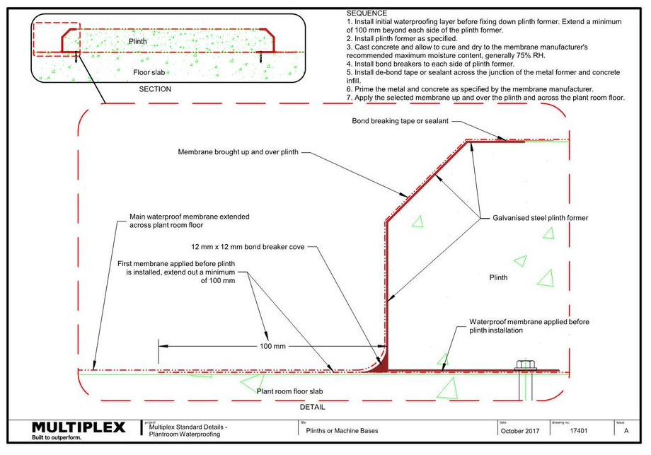
17401 - Plinths or Machine Bases
17402 - Slab Edge With Engaged Plinth - Plan
17403 - Slab Edge With Engaged Plinth - Section
17404 - Penetrations - Section
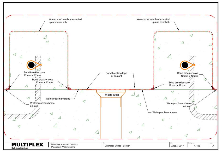
17405 - Discharge Bunds - Section
17406 - Typical Pedestal/Stanchion Details - Plans
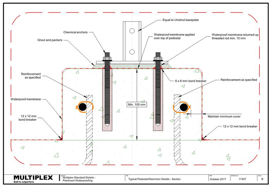
17407 - Typical Pedestal/Stanchion Details - Section
17408 - Permanent Form Work - Slab Edge - Section
17409 - Permanent Form Work - Floor Level Penetrations - Section
17410 - Permanent Form Work - Discharge Bunds - Section
Document Control
Version 02 July 2020