Podium, Roofs and External Plantrooms
Key Considerations
- Falls
- Material selection
- Preparation
- Installation and application
- Testing
Design
Podium and roof design must consider:
- Waterproofing to AS 4654
- Standard MPX 17200 series of drawings.
- Falls (not less than 1:100) to concrete slabs and be shown on each of the consultant's drawings eg. architectural, structural, and hydraulic drawings
- Slabs being designed to prevent the erosion of falls due to the long-term deflection occurring up to ten (10) years from completion of the project.
- Documenting falls
- Bunds/Hobs being provided around floor level penetrations.
- Conduits cast into slabs or walls spread apart with a minimum of 50 mm between each.
- Conduit that are fully enclosed by posts, columns or the like, cut not less than 100 mm above the top of the concrete.
- Conduits brought out via vertical surfaces and be angled down to ensure water drains away from the wall.
- Door openings to internal spaces incorporating a hob at a minimum 100mm above the external FSL and in accordance to AS 4654 for threshold heights
- Stair thresholds having the concrete ramped upwards to ensure water flows away from the stairs.
- Stair well edges incorporating a kerb minimum 100 mm high and in accordance to AS 4654 for threshold heights
- Floor wastes suitably arranged to prevent the creation of stresses in the slab that can result in cracking.
- Floor wastes being installed using cast iron or stainless steel floor wastes cast into the concrete
- Floor waste location to be coordinated to plant/ plinths
- Note: Electrical, mechanical and hydraulic penetrations from roof plant decks can be a source of water ingress into buildings. Be aware that water can travel along and within conduits, and within lagging and insulation of pipework from external plant areas to internal areas.
- Light pole, steel framing and any post installed item fixed to the concrete must be installed on a concrete plinth at minimum 150 mm high.
- Conduit cast in slab or walls must be spread apart with a minimum of 50mm between each. Conduit ends must be sealed to prevent water entry unless the conduit is fully enclosed by posts, columns, or the like.
- Concrete hobs must be installed around large service penetrations.
- Penetrations should where possible be installed at high points
- Plant and equipment located on a plant room or roof must be installed on a membraned plinth.
Podium and roof membranes must:
- Be tested to AS4654.1 & AS4858.
- Be in accordance with the membrane selection chart and membrane locations
- Consider and effectively document the maintenance requirements of the top coats to ensure warranties are not void
- Be protected by paving, concrete topping or stone ballast to protect the membrane where possible
Preparation
Concrete Preparation
- Concrete substrates must:
- Have falls 1:80 to 1:100 to the stormwater drainage outlet.
- Have a smooth finish
- Be prepared as specified by the membrane manufacturer.
- Confirm moisture content of substrate meets the requirement of the membrane manufacturer.
- Curing compound must not prevent adhesion of the selected membrane. Concrete may require additional preparation, e.g. grinding, shotblasting, etc., to remove contaminants.
- Prepare the concrete to remove:
- Form release agents
- High spots and sharp protrusions
- Loose or friable concrete
- Offsets
- Tie holes
- Blow holes greater than or equal to 2mm.
- Cracks greater than 1mm or as specified by the membrane manufacturer, must be routed out and filled flush with a sealant if specified.
- Where retrofitted flanges need to be installed they are to be finished level with or slightly below the concrete surface (cutting out or grinding of finished concrete as required), never higher.
- Ponding of water on the substrate must not be present. If there is water ponding on the substrate, the substrate may need to have a topping screed laid to falls before laying the membrane to remove ponding, or additional drainage may need to be installed to drain the ponded water or any other method to avoid ponding.
Application
Priming
Primers must be:
- Applied as per manufacturer’s guideline
- Covered within the nominated timeframe
- Applied with the required moisture content
- Compatible with substrates, including leak control flange and other components
- Only applied when the air temperature is higher than 5 degrees or as specified by the manufacturer.
Membranes
Membranes must be:
- As per the approved sample
- Applied as per manufacturer’s instructions taking account of the factors that might impact the membrane performance (e.g. moisture content of the concrete, relative humidity, temperature).
- Not applied when temperature is lower than 5 degrees (refer to manufacturer’s guidelines).
- Do not apply a membrane when rain is forecast during the curing period
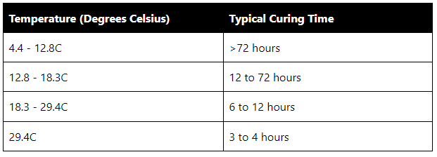
- Applied with consideration to the curing time where temperatures are lower than 10 degrees or higher than 30 degrees.
- Completely dry before curing can commence, and flood testing or toppings are applied.
Notes:
- Failure to observe this requirement can lead to membrane re-emulsification that requires expensive remedial work.
- There is a fundamental difference between a touch dry membrane and a cured membrane.
- When preparing programs, this time frame must be allowed for.
- Weather and other environmental factors will influence the time it takes for drying and curing.
- Cold and wet = long time to dry and cure.
- Hot and dry = fast drying and curing.
- Enclosed perimeter with little to no cross ventilation = slow drying and curing.
Table 1: Example temperatures and time for curing
Film Thickness
All membranes, both sheet and liquid, rely upon the final film thickness to be able to function as designed. The correct thickness ensures the mechanical properties will be preserved and the membrane will be durable and perform the desired function.
- Liquid membranes must:
- Be tested with a comb during application to determine the wet film thickness as per Figure (Note: A membrane with 50% solids applied at a thickness of 2mm out of the can will dry out to 1 mm DFT).
- Be tested using an ultrasound device for cured acrylic and polyurethane membranes to determine the dry film thickness. For cured cementitious membranes a destructive test must be conducted, with a minimum of one test and an additional test conducted for each 10m2 chosen at random.
- Have records of wet and dry film thickness values recorded in the Sub-contractors Checklists.
Spark/Holiday Test
Spark/Holiday testing (in lieu of flood test) must be:
- Conducted when the selected membrane is compatible ie. polyurethane
Tensile/Pull Off Test
Tensile/pull off tests must be:
- Conducted for all external applied membranes where solvent borne polyurethanes, plural component elastomers are applied and screeds are not applied
- Conducted at frequencies based on a risk assessment or as follows:
- Greater than 10 m2 and less than 30m2 – 2 test sites
- Greater than 30m2 and less than 100m2 – 3 test sites
- Exceeding 100m2 – 3 test sites plus 1 test site for each additional 100m2
UV Protective Coatings and Slip Resistance
- Applied as per manufacturer’s guideline
- Applied to membrane within the nominated timeframe
- Applied once membrane has cured and surface is dry
- Only applied when the air temperature is higher than 5 degrees or as specified by the manufacturer.
- Achieve the requirement of the UV protection underlying membrane
- Achieve requirement Slip resistance for all trafficable area I.e. on top of lift
Joints
What are temporary movement, permanent movement and construction joints?
Temporary movement joints are deliberate discontinuities in structural members, usually slabs and beams, that allow initial shrinkage of concrete to take place. These joints are then locked together at a point in time specified by the structural engineer. Locked together, they continue to transfer shear, but prevent further movement taking place.
Permanent movement joints are deliberate discontinuities between structural members, usually slabs and beams. they are provided to allow movement of the structure for long and short term effects such as thermal movement and long term creep. Permenant movement joints are notorious failure points in a waterproofing system. Changes in direction should be avoided in the structual design if possible.
A construction joint (a.k.a. a cold joint) is an interface between two concrete pours.
Waterproofing of joints often fails because of an insufficient allowance for movement in the membrane system.
Temporary Movement and Construction Joints
Even when locked, minor movement will continue and will need to be considered in the waterproofing system.
Construction joints and temporary joints in substrates must:
- Be saw cut or routed out,
- Have bond breakers installed to allow for ongoing movement.
Permanent Movement Joints
Permanent movement joints must:
- Have elastomeric bandages
- Be confirmed with the structural engineer or slab designer to determine the maximum expected movement at the joint, and ensure sufficient slack loop remains in the bandage to accommodate this movement.
- Have consideration for changes in direction and transition
- Ensure substrate to which it is affixed is cleaned and primed
- Ensure waterproofing is immediately protected from mechanical damage
- Have gutters (PVC or stainless) installed under permanent movement joints.
Services Penetrations
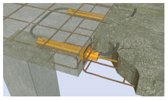
- Electrical conduits and irrigation pipes must be raised above the base (not less than 50mm) with sufficient separation to allow the application of membrane in between (nominal 50mm).
- Be limited in number.
- Be installed in conduits with all joints and ends sealed.
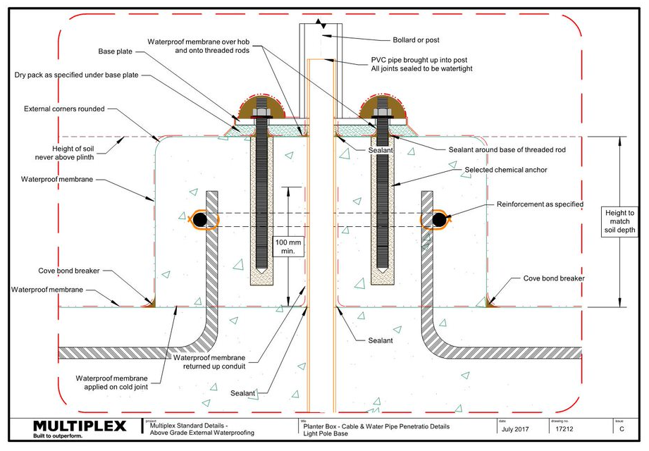
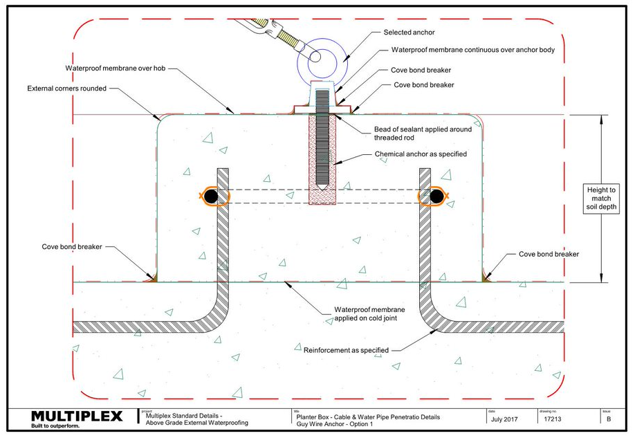
Steel posts, Columns, Light Poles, Guy Wires and the Like
Steel posts, columns, light poles, guy Wires and the like must be:
- Installed on plinths of reinforced concrete, refer to 17213 for Guy Wire details
- On hobs raised as high as practicable, refer to 17212 for post details
- Held down only with chemical anchors
- Waterproofed before and after casting plinth.
Multiplex Standard Details
Podiums, Roofs and External Plantrooms
17216 - Typical Cold or Temporary Movement Joint - "Triple Detail"
17217 - Flat Roof - Typical AC Duct Penetration
17218 - Flat Roof - Typical Pipe Penetrations
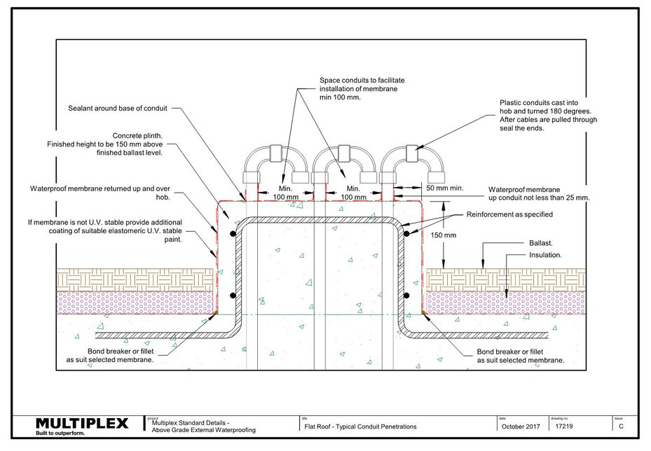
17219 - Flat Roof - Typical Conduit Penetrations
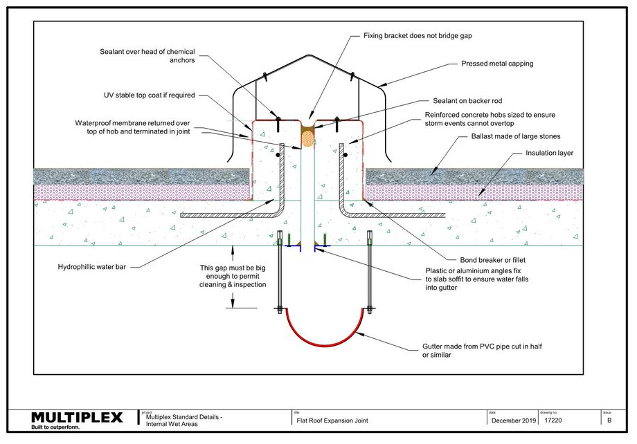
17220 - Flat Roof - Expansion Joint
17225 - Flat Roof Typical Anchor Point Detail, Section
17226 - Siphonic Stormwater Drainage – Geberit Pluvia - Plan
17227 - Siphonic Stormwater Drainage – Geberit Pluvia - Section Surface Fixed
17228 - Siphonic Stormwater Drainage – Geberit Pluvia - Enlarged Edge Detail - Surface Fixed
17229 - Siphonic Drainage – Syphon Systems - Cast In - Plan
17230 - Siphonic Drainage – Syphon Systems - Cast In - Section
17231 - Movement Joints - Permanant, Using Ardex Butynol Strip
Document Control
Version 02 July 2020
Version 03 Nov 2023 Incorporation of additional considerations relating to falls and membranes.