Design
Design Considerations
Access and Maintenance
- The design of the architectural layout of the pool hall / area shall allow for safe and compliant access around the pool including any necessary regular maintenance access (i.e., access to skimmer boxes) to eliminate the need for maintenance personnel to enter the water body to perform the require maintenance works.
- Consideration shall also be given to construction access and tolerance to enable the construction / installation of the pool.
- Consideration shall be given to general maintenance access in particular operating any access equipment around a waterbody.
- Where the use of spring type mounts is specified by the acoustic consultant, consideration must be given in the design of the pool hall layout, pool shell design and surrounding host building structural design (i.e., concourses) to enable access for spring mount maintenance access and future replacement noting springs generally have a warranted operational life of 10 years.
- Where the design constraints to not permit such access provisions, consideration shall be given to the use of natural rubber bearings or other products that have a longer operational life whilst maintaining equivalent performance.
Lighting
- All swimming pool light fittingsmustbe supplied with pre-terminated cabling at a length as required to reach the driver or consolidation point.
- It is important to plan for this, as it is likely that lead times will be longer when procuring fittings with longer cabling.
- Drivers and consolidation pointsmustbe located above the swimming pool water level.
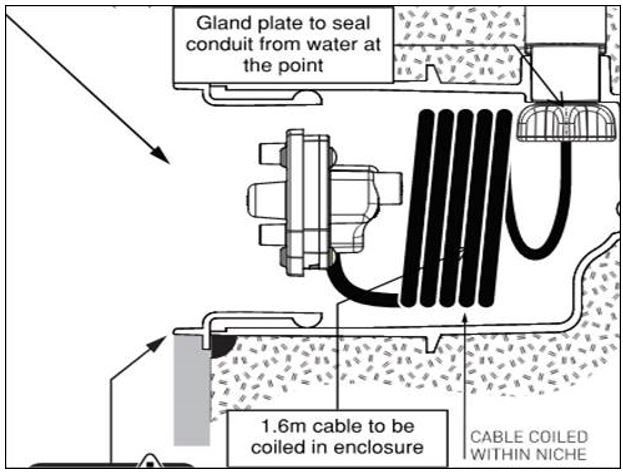
- Where this is not possible, an air loopmustbe formed in the conduit(s) so water cannot drain back to the driver/consolidation point location.
- Driver/consolidation point locations to be coordinated as required to suit the light fittings’ cable length – which at times may be limited by voltage drop.
- Cable joints are not accepted behind light fittings; all cabling must be radial
- Daisy chaining or ring circuits are not permitted for this installation.
- Sufficient cable length needs to be provided at each fitting as required to allow the removal of the fitting for maintenance above the water level.
- The additional cable length may need to be coiled up at the driver/consolidation point location due to space limitations behind the light fittings.
- Conduits are not to be sealed behind the light fittings, to ensure free movement of the cabling for maintenance/replacement.
- Light fittings are not to be sealed with the use of silicone or the like to the pool surface.
- Applying silicone to the fittings makes maintenance difficult and will prevent new light fittings from seating correctly against the pool surface.
Pool Plant and Storage
- The building architectural design shall provide appropriately sized and positioned consolidated pool plant area to accommodate pool filtration, treatment and heating plant as required.
- In addition, the design shall consider the provision of pool side cupboard storage to house cleaning equipment, removal access hoists etc.
Pool and Spa Layout and Safety Compliance
- The design of the pool and/or spa layout shall consider safe and compliant entry into and out of the waterbody.
- Unless dispensation is provided by the project access consultant and building surveyor / certifier, compliance with NCC 2019 Volume 1 and AS1428.1-2021: Design for Access and Mobility, Part 1: General Requirements for Access – New Building Work.
- Treads on ladders must:
- provide a non-slip surface
- be designed and installed so that they cannot trap or injure the swimmer.
- All ladders should be provided with a dual top tread.
- Poolside barriers must be:
- Designed, manufactured, and installed in accordance with AS 1926.1:2012, “Swimming pool safety Part 1: Safety barriers for swimming pools”
- Located in accordance with AS 1926.2:2007, “Swimming pool safety Part 2: Location of safety barriers for swimming pools” or as otherwise required by local Regulations
- Installed to prevent the possibility of bathers being trapped.
Acoustic Isolation and Structural Considerations
- The design shall consider all acoustic isolation and performance requirements between the pool shell and the host building structure as specified by the project acoustic consultant.
- Other than in-ground pools, unless approved otherwise by the acoustic consultant, the surrounding concourse structure shall be kept independent of the pool shell.
- The design of the pool shell structure shall consider the cases where the structure is full of liquid and when it is empty.
- For in-ground pool shells, the design shall consider backfill loads including during placement and compaction (where required) of backfilling materials.
- Similarly, loading from construction vehicles and machinery intended to be operated in the vicinity of the pool shall also be considered in the design of the pool shell.
- Since the passive resistance of the earth is never certain, it should be ignored when designing the structure when it is full of liquid.
Pool Floor and Surface Design
- Any required change in depth of the pool floor shall generally be achieved by the provision of an even grade no steeper than 1 in 20 unless the intended pool use requires a steeper grade.
- Any such change in grade or any stepped edge shall be marked within the pool finish through the provision of a 30% contrasting coloured edge with a minimum width of 55mm along the full length of the grade / level change.
- The design shall consider the provision of:
- appropriate and code compliant slip resistance to all surfaces within the pool and surrounding the pool.
Water Quality and Thermal Considerations
- Thermal blankets to pools and spas noting that for external pools and spas the provision of thermal blankets is mandatory under the requirements of NCC 2019 Volume 1.
- Only potable quality water shall be permitted for use for pool / spa make-up water.
- The use of harvested roof stormwater is not acceptable unless it is first filtered, treated and brought up to potable water quality.
Construction Materials and Methods
- The use of Bondek or any other metal decking lost form systems is not permitted for use for pool/spa shell construction.
- The use of Bondek or any other metal decking lost form systems is permitted for use in the construction of surrounding host building elements such as pool concourse slabs, only where the slab design does not rely on the composite action of the form system in the permanent load case.
- Additionally, the environment that the form system will reside in, shall be considered for the provision of ventilation and drainage.
- The use of Bondek or any other metal decking lost form systems for use in suspended floors above pools/spas is subject to further review of the environment (e.g. humidity) and encapsulation conditions.
Concrete Pool Shell Design
Every project must engage an Engineer who has suitable qualifications and proven experience to design the pool structure. The engaged Engineer is to provide the relevant professional registration(s) and insurances as required by the specific State in which the works are being administered that enables the Engineer to provide the appropriate design certification.
- The design of a concrete pool shell shall be in accordance with AS 3735-2001: Concrete Structures for Retaining Liquids and AS 3600-2018: Concrete Structures unless approved otherwise.
- Design certification of the pool shell must be provided by the engaged Engineer.
- The use of Bondek or any other metal decking permanent lost form systems is not permitted for use in the construction of pool / spa shell.
- The design and construction of the concrete shall be such that the concrete vessel is watertight. The design of the pool shell must not rely upon the waterproof membrane for the structure’s watertightness, cover to embedded reinforcement, or durability requirements.
- Reinforcement detailing including the lapping, splicing and projection of bars or mesh shall be compliant with the relevant Australian Standards as noted above.
- All reinforcement shall achieve a minimum 50mm cover of concrete from the concrete face in contact with the waterbody, and a minimum of 40mm cover concrete everywhere else.
- The design shall consider the appropriate detailing, specification and use of proprietary water-stops across all construction joints within the pool shell.
- The use of Xypex or equivalent additives is not permitted within the pool shell concrete mix. Refer to Section 3.1.10 for all other concrete mix design requirements.
- The pool shell must be hydrostatically tested prior to any application of membrane products or applied surface finishes. Refer to Testing section for hydrostatic testing details.
Fibreglass and Stainless-Steel Shell Design
- Fibreglass spas constructed within a concrete shell must:
- Be watertight to prevent leakage into the concrete shell containing them.
- Have suitable slip ratings to any trafficked surfaces within the shell in accordance with the relevant codes and standards.
- Have an appropriate structural design certification and warranty from the manufacturer / supplier.
- Be installed, supported and backfilled in strict accordance with the manufacturer’s specifications and requirements.
- Have adequate provision for maintenance access.
- Be provided with appropriate membrane and drainage within the host concrete shell that is directed to the sewer in the event of any spillage or leakage from the fibreglass shell.
- Stainless steel pool / spa shells constructed within a concrete shell must:
- Be watertight, once the appropriate liner system has been installed to prevent leakage.
- Have suitable slip ratings to any trafficked surfaces within the shell in accordance with the relevant codes and standards.
- Have an appropriate structural design certification and warranty from the manufacturer / supplier.
- Be installed by an authorised and accredited contractor as specified by the stainless-steel shell manufacturer and must be supported in strict accordance with the manufacturer’s specifications and requirements.
- The pool shell must be hydrostatically tested upon completion of the installation and application of the appropriate liner system. Refer to Testing section for hydrostatic testing details.
Fresh Air
- All indoor pool locations are recommended to have:
- A minimum of 10 I/sec of fresh air per person
- 3 l/sec/m2 of pool area.
- It is recommended a slight negative pressure within the pool hall should be created to minimise moisture migration to adjacent rooms and to reduce the possibility of moisture vapour being driven into the building fabric.
Pool Plant Room Ventilation
- Any enclosed pool plant room shall be provided with a minimum 12 air changes per hour through mechanical or natural ventilation as designed by the engaged Mechanical Engineer.
- Where condensing gas boilers are located within the pool plant room, the Mechanical Engineer shall design the ventilation to provide the necessary combustion and dilution of air as well as all flue requirements to vent external to the building to comply with the relevant gas regulations and codes.
Humidity Control
- Humidity levels in an indoor pool should typically be controlled below 65% RH, with below 60% being preferred.
- The pool hall air temperature should generally be set at 1 degree Celsius above the set water temperature of the main pool to an air temperature upper limit of 31 degrees.
Condensation Control
- There are four main considerations in preventing/minimising condensation:
- Good building design eliminating cold bridging
- Keeping air moving across potentially cold surfaces
- Maintaining ideal relative humidity (55% - 65%)
- Installing of an adequate vapour control layer.
Ventilation of Spa Humidity
- A spa pool must have sufficient exhaust air capacity to continually extract or be boosted to cater for the jet/blower function.
- Where a spa is installed in the same hall as a swimming pool, the spa must be provided with a separate air/condensate extraction immediately over the spa.
Air Distribution, Ductwork and Grilles
- Air distribution systems are installed to ensure even distribution and consequently uniform air temperature and humidity throughout the conditioned space, and to direct warm dry air on to any surfaces liable to condensation.
- The air distribution scheme should be designed to ensure a curtain of conditioned air encompasses all area of potential dew point condensation such as windows.
- Corrosion resistant materials must be used.
Interstitial Condensation Control
- It is essential to provide the space above the ceiling as a mechanism to “breathe” the ambient air allowing the moisture to escape and not concentrate.
- Alternatively, to prevent condensation adequate forced ventilation within the ceiling void above must be provided.
Ceilings
- Due to the environment of the space, a specific design from the manufacturer is required.
- The manufacturer’s advice as to the arrangement and spacing of any required expansion joints in the ceiling must be adhered to, NOT to the architect’s vision.
Walls
- Walls within 500 mm of the pool edge must be waterproof to a minimum height of 1800mm, and tiled.
- Walls within 2000 mm of the pool edge should be waterproofed to a minimum of 1200mm, and tiled.
- Glazing may be used, but: must:
- Finish on or above the floor
- Be accessible for cleaning without entering the pool.
- Aluminium framing must not be embedded in the floor screed.
Adjacent Rooms to a Pool Hall
- Provision must be made for adequate heating and ventilation of any rooms adjoining the pool hall, such as changing, toilet or storage areas, to prevent localised condensation.
Pool Surround
- The most important consideration to be given to the pool surround is safety.
- An anti-slip surface is essential, but other aspects should be addressed. The following criteria should be taken into account:
- Levels to fall away from the pool or into a drainage gully to prevent re-entry of contaminated water.
- Falls must never exceed 1:40.
- The use of covings to enable cleaning right into the corners.
- Surfaces able to be accessed safely for cleaning.
- Surfaces able to be cleaned, e.g., anti-slip tiles need to be mopped, without shredding the mop and leaving sections of the profile dirty.
- Provision of fresh water taps for facility cleaning.
- Provision for safely changing any light fittings without having to enter or empty the pool.
Balance Tanks
- The balance tank itself should be constructed:
- to the same strength and thermal conductivity value as the pool
- to ensure internal surface of the channel is watertight and finished in a material which is easily cleaned.
- Where space etc. is at a premium, then an appropriate prefabricated tank/s can be used, providing there is access for cleaning etc.
- The balance tank shall be sized by the engineer or contractor responsible for the pool filtration design and shall successfully provide the following:
- A minimum depth over the sump / draw point and a minimum volume of water to enable standard operational draw of water from the tank through the filtration system without the system ever drawing air due to low water level.
- Design that considers the necessity of an anti-vortex plate or other form of protection.
- A minimum volume of water to enable filtration backwashing operations without lowering water levels within the tank below the minimum depth required for standard operational draw.
- Sufficient freeboard volume to accommodate peak bather load within the pool at any given time.
- For outdoor pools only, an appropriately calculated freeboard volume to accommodate heavy rainfall events to avoid regular overflowing of the tank.
- A minimum of 100mm from the top of water level calculated from all of the above requirements to the invert level of the balance tank overflow point. Note that the overflow is to be connected to the sewer outlet unless approved otherwise.
- The balance tank should incorporate:
- A ventilation pipe or pipes installed to allow external venting to avoid the build-up of chemicals in the balance tank atmosphere.
Concrete
- The pool / spa concrete mix shall be specified by the engaged engineer responsible for the pool shell design. As a minimum, the concrete mix shall satisfy the following requirements:
- Concrete compressive strength for the pool structure must be a minimum of 40 MPa at 28 days or as specified by the engineer, subject to the minimum cement content requirement specified below.
- Maximum water/cementitious ratio = 0.45. Minimum effective cement content = 350 kg/m3
- Unless approved otherwise, aggregate size shall be 20mm.
- The finished concrete must be dense, durable and highly impermeable.
- The pool concrete must contain not less than 5% of silica fume or an approved alternative.
- Maximum drying shrinkage of pool concrete must be limited to 700 microstrain at 56 days.
- Xypex or similar additives must not be used under any circumstance.
Structural Layout - Pour Breaks
- It is essential for the designer to consider the method of construction and to specify on the drawings the position of all construction and movement joints.
- The following are to be considered:
- Provision of ‘kickers’ or short sections of upstand concrete 100 to 150mm high against which formwork may be tightened,
- Size of wall and floor panels to be cast in one operation.
- Where structural stress relief joints are considered necessary in construction, they must be sealed on the water face and a water stop provided.
- When tiles or mosaics are laid, all movement joints must be taken through the tile bedding to the tile surface.
In-Ground Pools
- Must always be built:
- On a concrete blinding slab with a smooth near steel trowel finish.
- With 2 layers of 200 um high impact resistant plastic sheets:
- With all joints lapped 200 mm
- Sealed with waterproof tape.
- The design shall consider sub-surface drainage including perimeter ag-lines and an approved drainage cell that is placed over the blinding layer. Subject to the presence of a water table as determined / advised by the engaged geotechnical engineer, the design shall consider the provision of hydrostatic relief valves cast into the pool base slab.
Document Control
Version 01 October 2021