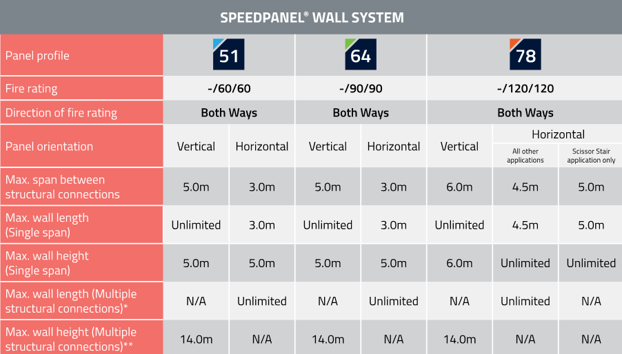
Speed Panel Walls
Key Considerations
- Compartmentation Plans - Fire & Smoke
- Fire Resistance Level (FRL)
- Element Material FRL (i.e. wall, floor, ceiling)
- Service Material FRL (i.e. penetrating a compartment, FRL)
- Fire/smoke stopping system (as per MPX schedule)
What is the Speed Panel wall system?
Speed Panel is a fire and acoustic rated wall system. Each panel is made from a light gauge steel shell that is filled with a lightweight aerated concrete core. The roll-formed steel outer shell is made by two separate halves that are pressed together.
Why use Speed Panel?
- Lighter loads on the structure compared to traditional masonry products.
- Reduced structural sizes together with speed of installation that results in cost savings compared to traditional masonry construction.
- Thermal resistance performance and effective sound transmission barriers between external and internal environments of the buildings
- Fire rating properties with fire resistance levels (FRL).
- One sided construction.

Click on the image for an enlarged view
Framing
Head, Base and Side Track
Tracks must be:
- Installed in accordance with Speedpanel installation guide and details. Refer to Speedpanel:
- Head details
- Base details
- End Details
- Fixed with M6.5 x 50mm Mushroom Head Spikes into the structure at 500mm centres (or approved sample).
- Applied with a continuous approved fire rated sealant in-between track and structure for the entire perimeter (Refer figure).

Click on the image for an enlarged version

Click on the image for an enlarged version

Click on the image for an enlarged version
Panels
FRL and Heights
Refer to the table below as a guide to the FRL that may be achieved for the nominated wall heights and details provided for the respective wall types
Horizontal Installation
Fix panels:
- Vertically at 250mm centres at the perimeter.
- Horizontally at 500mm centres at the perimeter.
- At every Panel joint, vertically at 250mm.
- Horizontally at 1000mm centres.
Each panel must interlock before fixing to ensure fire rating and acoustic properties are maintained.
Horizontal Corners and Intersections
Horizontal corners and intersections must be:
- At intersecting panels at 900mm centres
- At intersecting corners with 10D x 16mm SDS
- Installed in accordance with the Figure
- Installed in accordance with Corner and Intersection Details
Vertical Installation
Panels (up to 5m in height) must be fixed:
- Horizontally and vertically at 500mm centres at the perimeters.
- Vertically at 1000mm centres in the body of the panels.
- At every panel joint, horizontally at 250mm
Vertical Corners and Intersections
Vertical corners and intersections must be:
- At intersecting panels at 900mm centres
- At intersecting corners with 10D x 16mm SDS
- Installed in accordance with the Figure
- Installed in accordance with Corner and Intersection Details
Vertical Wall Connection
Vertical wall connection must be:
- Installed in accordance with the figure.

Click on the image for an enlarged version

Click on the image for an enlarged version
.png)
Click on the image for an enlarged version
.png)
Click on the image for an enlarged version

Click on the image for an enlarged version
Penetrations
Vertical System Penetrations
Structural Adequacy
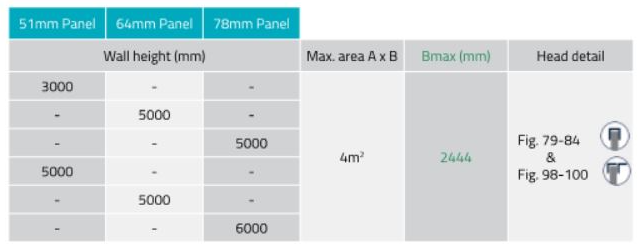
Vertical systems can have rectangular or square penetrations up to 4m2. Refer to Table and Figure.
Note that although the wall is approved to support large openings, the maximum size penetration system is limited to the passive fire material manufactures fire testing. Eg Trafalgar FyreBATT is approved in Speedpanel for sizes up to 1200 x 600 mm (W x H).
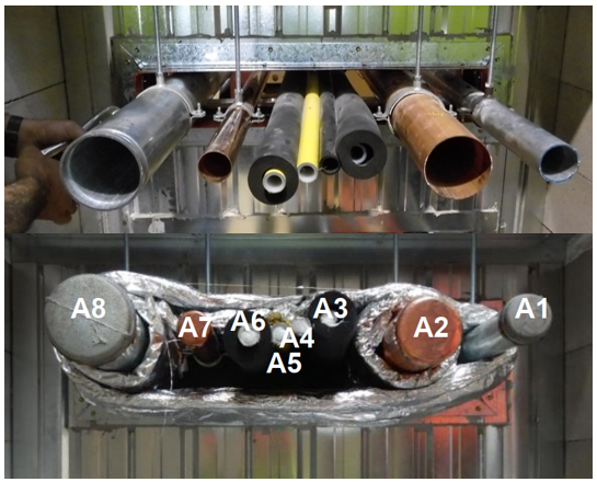
Where multiple small services run through a wall, these can be considered to be grouped into a rectangle with a total area not exceeding 4m2. Refer to the Table below and Figure. Please note as above, the material used to close down the penetration must also be approved at the maximum size. In practice the smaller the aperture, the safer and easier it will be to achieve a Deemed to Satisfy penetration system!

-be5a6122.png)
Click on the image to view an enlarged version
.png)
Click on the image to view an enlarged version

Click on the image to view an enlarged version
Horizontal System Penetrations
Structural Adequacy
Horizontal systems can handle penetrations up to 4m2. Refer to Table and Figure.
Where multiple small services run through a wall, these can be considered to be grouped into a square or rectangle with a total area up to 4m2. Refer to the Table above and Figure.
.jpg)
Click on the image to view an enlarged version

Click on the image to view an enlarged version
.jpg)
Click on the image to view an enlarged version
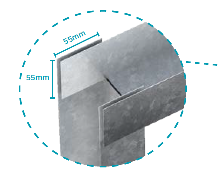
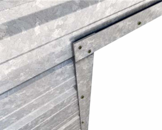
Corner Fixing
- “C” track is to be notched out as shown 55mm into each end of the C-track.
- Use 10 gauge self drilling screws and fix into the corners at 45° as shown.

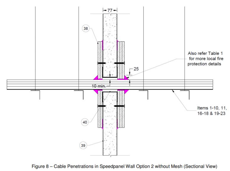
Cable Penetrations
Single Cable
Single cables must be:
- Installed in accordance with the evidence of suitability which should:
- Have a min of 50mm separation between any other drilled penetration (ie. single, bundled cable or insulated penetration) or as specified eg fire dampers.
- Have a min of 200mm separation between any other formed penetration or as specified.
- Be sealed with a sealant that is tested to AS1530.4-2014 with the same cable/bundle sizes.
Bundled Cables
Bundled cables must be:
- Installed in accordance with the evidence of suitability which should:
- Have a min of 50mm separation between any other drilled penetration (ie. single, bundled cable or insulated penetration) or as specified.
- Have a min of 200mm separation between any other formed penetration or as specified eg fire dampers.
- Be sealed with a sealant that is tested to AS1530.4-2014 with the same cable/bundle sizes.
- Consider the maximum size of bundled cables.
- Be fixed with steel fasteners (surface mounted collars only).
- Be fixed with fire grade plasterboard sheets (where required).

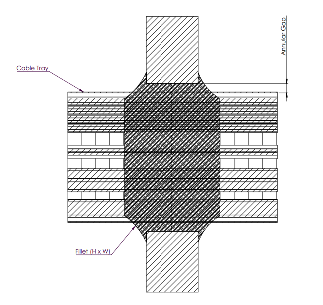
Cables on Trays
Cable trays must be:
- Installed in accordance with the evidence of suitability which should:
- Have hangers installed 150mm maximum from either side of the wall.
- Have wrapping 600mm either side of the cable tray to maintain insulation criteria or 2mm steel mesh.
- Have a min of 50mm separation between any other drilled penetration (ie. single, bundled cable or insulated penetration) or as specified.
- Have a min of 200mm separation between any other formed penetration or as specified.
- Have the installation fire grade plasterboard sheets (where required).
- Have a minimum 10mm clearance between cable tray and aperture surface.
Conduits
Conduits must be:
- Installed in accordance with the evidence of suitability which should:
- Have either a intumescent sealant or fire collar fixed with steel fasteners
- Be smoke sealed internally when passing through 2 compartments or more
- Have a min of 50mm separation between any other drilled penetration (ie. single, bundled cable or insulated penetration) or as specified eg fire dampers.
- Have a min of 200mm separation between any other formed penetration or as specified.
- Most fire stopping systems in Speedpanel walls require additional patching to prevent heat transfer from occurring through the metal channels around the penetration. Refer to induvial penetration test or assessment reports for clear detailing on such requirements.
Note: size limitations may apply to some fire stopping systems:
- Promat Conduit Collar = Max. 32mm conduit.
- Trafalgar Fyrechoke Conduit Collars = Max. 40 mm conduit
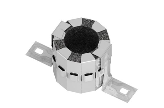
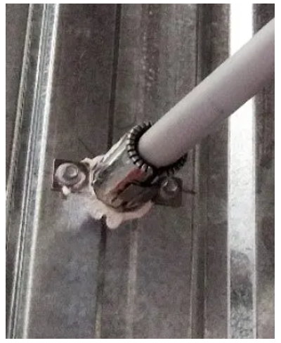
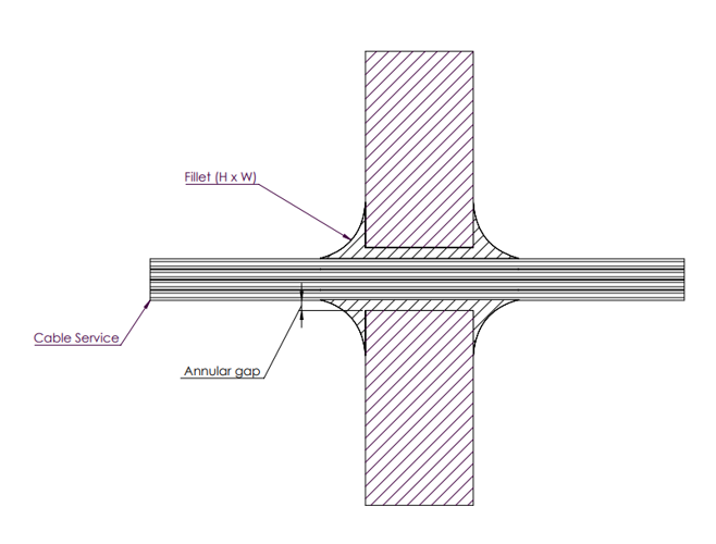
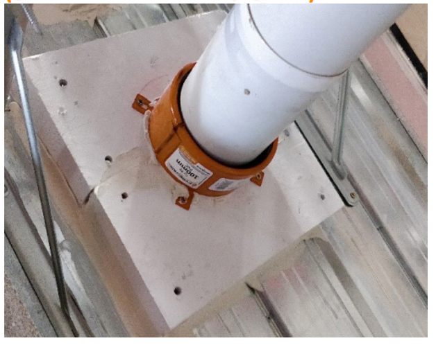
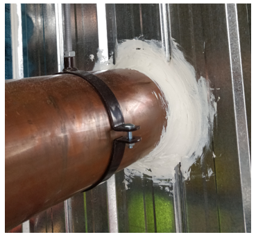
Hydraulic Pipework
Combustible ie. PVC
Combustible pipework must be:
- Installed in accordance with the evidence of suitability which should:
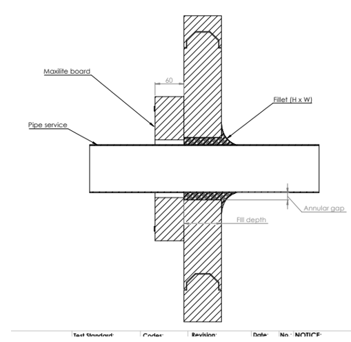
- Be installed with a retrofit collar or through collar (in wall-type) as per evidence of suitability (Refer Figure for an example)
- Have a 10-15mm annular gap
- Be sealed with a sealant that has been tested along with the fire collar.
- Have a min of 50mm separation between any other drilled penetration (ie. single, bundled cable or insulated penetration) or as specified.
- Have a min of 200mm separation between any other formed penetration or as specified.

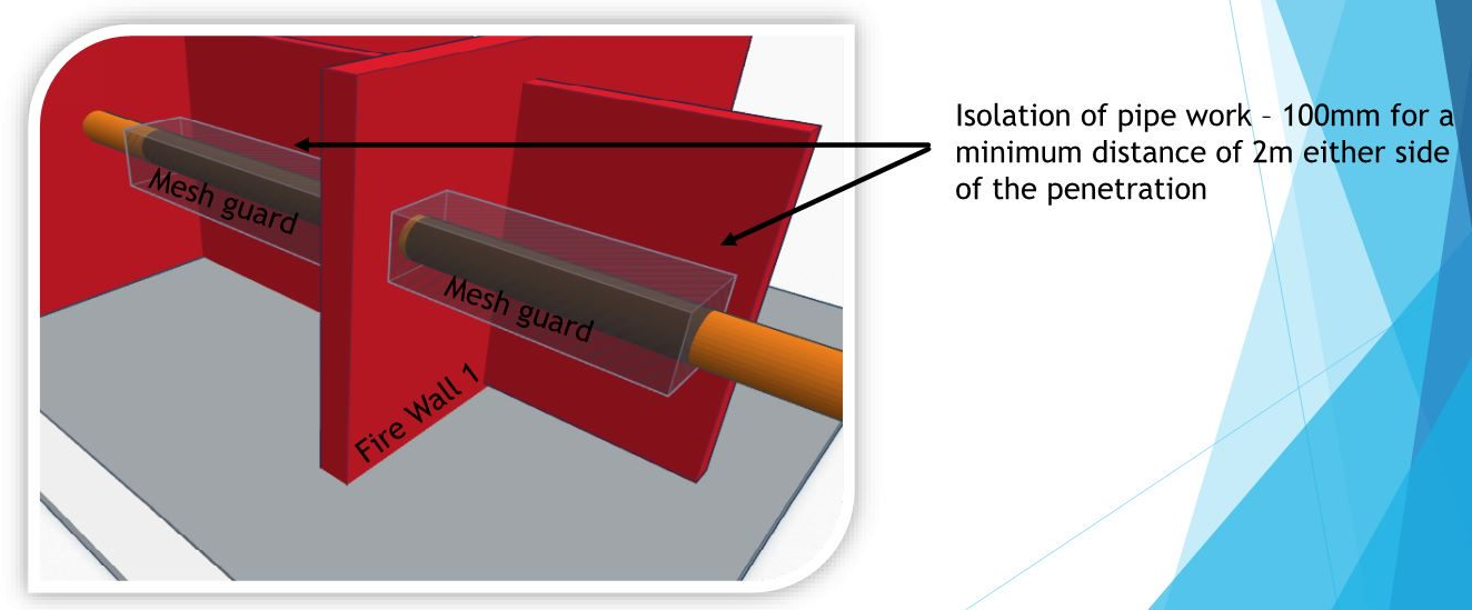
Non-Combustible ie. Copper
Non-combustible pipework must be:
- Installed in accordance with the evidence of suitability which should:
- Have a minimum 100mm clearance around the pipe from any combustible material for a length of 2m vertically or horizontally (refer to Figure below regarding the use of mesh guards) or
- Be wrapped with insulation to maintain FRL insulation criteria using a wrap material that has been tested as part of the same system with the sealant (or other product) used to seal the pipe to the wall.
- Be sealed with a sealant that has been tested and approved for use in Speedpanel walls specifically, along with the required wrapping material eg Trafalgar FyreFLEX sealant and TWrap (refer to figure below)
- Have a min of 50mm separation between any other drilled penetration (ie. single, bundled cable or insulated penetration) or as specified.
- Have a min of 200mm separation between any other formed penetration or as specified.
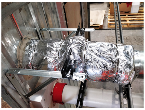
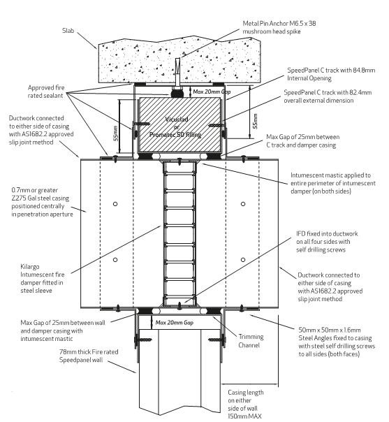
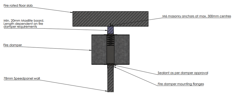
Fire Dampers
Fire dampers must be:
- Installed in accordance with the evidence of suitability which should:
- Have hangers installed 150mm maximum from either side of the wall.
- Have a min of 50mm separation between any other drilled penetration (ie. single, bundled cable or insulated penetration) or as specified.
- Have a min of 200mm separation between any other formed penetration unless the wall has been designed for structural adequacy to allow for openings to be closer as per AS1530.4.
- Have a min of 75 mm clearance between adjacent walls or slab soffit unless tested or assessed specifically.
- Installed as per section Fire Dampers.
Where fire dampers are being installed within 75mm of the soffit, Maxilite or other material filling must be installed in accordance with the evidence of suitability. Refer example in Figure.

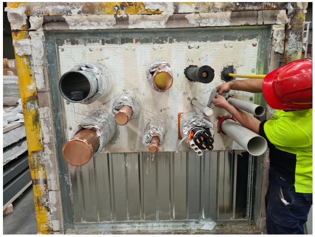
Multi-Services
Multi-services through one penetration utilising the TBA Firefly Intubat must:
- Be installed in accordance with the manufacturers’ installation details. Refer to manufacturers for installation details.
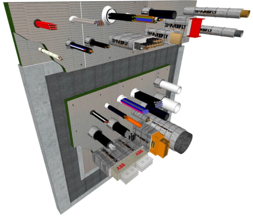
Multi Services Box
Multi-services through one penetration utilising the BOSS Fire® Transit Box or Trafalgar FyreBOX must:
- Be installed in accordance with the manufacturers’ installation details.
- Have services tested and achieve the required FRL.
- Have sealant applied to the ribs of speedpanel behind the mounting flanges.
- Evaluated for smoke leakage.
Document Control
June 2024 – General updates relating to pipework, fire dampers, conduits and multi services box