Grooved Pipework Incorporating Couplings, Fittings and Valves
Informative
What is a Roll Groove Pipe system?
A roll groove pipe system is a method of mechanically forming a groove into the end of a pipe, typically for joining purposes. This system involves the use of specialized equipment to create a groove or indentation along the outer surface of the pipe, allowing for the insertion of a coupling or fitting. The groove is usually created by rolling or pressing a grooving tool onto the pipe.
This type of system is commonly used in piping installations where quick and efficient joining of pipes is required. The grooved ends of the pipes can be connected using couplings that match the groove profile. Roll groove pipe systems are known for their ease of installation, versatility, and the ability to accommodate movement and flexibility in the piping system.
Roll grooving is often employed in various industries, including fire protection systems, HVAC (heating, ventilation, and air conditioning), water distribution, and other applications.
What is a Grooved Pipe Joint?
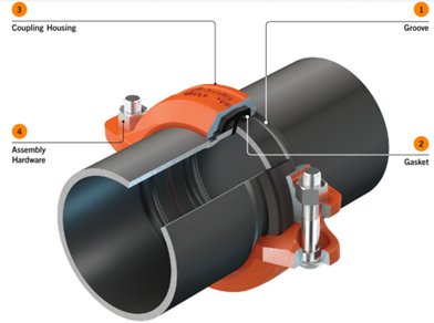
A grooved pipe joint consists of four elements.
- Grooved Pipe
- Typically made of Carbon Steel and sometimes Stainless steel, (other types available). The pipe may be galvanized, painted or uncoated, depending on service and external environmental factors. Grooves on the pipe can be:
- Cold formed (roll grooved with a hydraulic press action), which is the most common method, or
- Machine formed (cut grooved, not covered in this document; seek manufacturer's assistance).
- Gasket
- Various types and materials are available for different fluids, generally made of some type of EPDM. The gasket, enclosed by the coupling housing, wraps around the two pipe ends, and the coupling housing key sections engage the grooves.
- Coupling housings
- Typically made of cast ductile iron material. Coupling housings may be painted, galvanized, or sometimes stainless steel for harsh environments.
- Nuts & bolts
- Generally made of zinc, galvanised or sometimes stainless steel. The coupling’s bolts and nuts are tightened with a socket wrench or impact wrench.
What is the difference between rigid and flexible pipe couplings?
Grooved pipe couplings are available in two styles:
Rigid couplings (more common):
- Used to join straight runs and fittings, including elbows, equal and reducing T’s, in line reducers or adaptors, and also valves/strainers and accessories.
- Securely holds the pipe ends with no movement, creating a rigid joint.
- Requires treatment similar to traditional pipe joints in terms of support and anchoring.
- Achieves rigidity at the joint through a variety of bolt pad styles/shapes depending on the design and locking mechanism. Examples of bolt pad styles include.
- Tongue & Recess which involves the use of protruding and indented surfaces on the coupling housings. The male component, known as the tongue, extends outward from one side, while the female counterpart, the recess, provides a corresponding indentation on the opposing side.
- Angle Pad which includes inclined surfaces on the coupling housings. These inclined surfaces, known as angle pads, engage with corresponding grooves on the pipe ends during assembly.
- Sawtooth which involves the use of serrated or toothed surfaces on the coupling housings. These serrations, resembling the teeth of a saw, interlock with the grooves on the pipe ends during installation.
Flexible couplings:
- Are utilised for engineered problem-solving scenarios, for example seismic or thermal movement designs, or accommodation of curvature or settlement/movement between structures, they may also be used for noise and vibration attenuation around rotating equipment.
- Careful attention to the design, support, and anchoring is required.
Roll Grooving Tools
- Roll grooving tools must:
- Be in good working order with the correct roll sets for the pipe size ranges that will be prepared for joining.
- Have records showing its condition and that safety checks are current.
- Roller operation must be hydraulic pumped either by hand or automatically (automatic) as this allows for a smooth and steady pressure to be applied to the pipe end during the forming operation.
- Hand (drop lever type equal to or similar to Ridgid 916) roll groove equipment must not be used. This restriction is imposed due to the speed at which the groove is formed is more difficult to control, if the operator applies too much pressure - too fast then something called pipe flare can occur, potentially compromising the sealing surface of the gasket. These types of tools are also more susceptible to causing “walk off” or worst case cracking the seam welds at the pipe end.
- Tracking rollers must be fitted, i.e., upper and lower rollers must fully engage to eliminate forward and backward linear movement of the pipe (to eliminate misalignment of rollers and shearing of pipe during rolling).
- Upper and lower rollers must match the pipe size being grooved. Rollers are suitable for a limited range of diameters and are marked as such.
- Rollers must be chosen to suit the material being rolled. Different materials may require specific rollers (e.g., chrome-coated rollers for thin-wall stainless steel pipes).
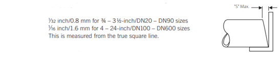
- Pipes must be cut square within published tolerances. Refer below.
Pipes
- Pipework quality must comply with the project specifications, and commonly referenced standards include:
- AS 4041 - Pressure piping
- AS 1074 - Steel tubes and tubulars for ordinary service
- BS EN 10216-1 Alloy Steel Seamless Tubes for pressure purposes
- BS EN 10217-1 Welded steel tubes for pressure purposes
- American Petroleum Institute Spec 5L Line Pipe
- ASTM A53/A53M Standard Specification for Pipe, Steel, Black and Hot-Dipped, Zinc-Coated, Welded and Seamless
- Fire Protection Pipe applications:
- Underwriters Laboratories (UL) - A third-party listing agency for product testing. UL verifies adherence to safety standards for a wide range of products, including those used in fire protection pipe applications.
- Factory Mutual Global (FM Global) - Primarily an insurance company that tests and approves components used in fire protection systems and other building elements. FM Global’s primary interest is in facilities they insure and in loss prevention/business continuity.
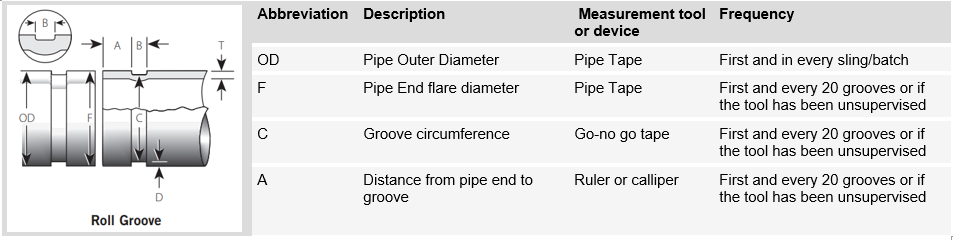
Roll Groove Critical Dimensions
- Pipe dimensions and groove dimensions must be within the tolerances specified in the manufacturer's tables to ensure proper joint performance.
- Some manufacturers have proprietary groove profiles with alternative tables of dimensions, in these cases different rollsets are required. These proprietary grooves are often designed to provide better performance on certain size ranges or types of pipes especially with thinner walls (less material so savings). Small diameter Fire Protection NB25mm or 350mm (all services) and larger are the sizes to look out for.
Roll Groove Inspections – Off-Site
- Inspections of completed roll grooves must be performed by suppliers of the grooved pipe spools from the pipe fabrication shop with a quality system of their own design that exceeds the below, or as a minimum as per table 1.
- Pipe spools must be marked to show the source, facilitating traceability and accountability in the inspection process.
- Records must be kept and be readily available for inspection upon request.
Roll Groove Inspections – On-Site
- When roll grooving is performed on site:
- Confirm the correct rollsets are available for the onsite tool, especially for larger diameters that may have a proprietary groove.
- Perform a visual inspection of the roll grooved pipework to check for any obvious defects, such as cracks, dents, or corrosion.
- Measurements as per Table 1 of completed roll grooves, must be carried out by experienced or trade-qualified subcontractors’ representatives who have been trained.
- Pipe ends must be marked to show that the groove was made and checked onsite.
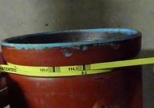
Figure 5 Example of the measurement of depth of groove.
Result: Over grooved – REJECTED
ACTION: end of pipe to be removed and discarded
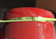
Figure 6 Example of the measurement of depth of groove.
Result: Under grooved – REJECTED
ACTION: More grooving required to achieve required depth
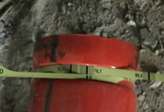
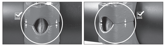
Figure 7 Example of the measurement of depth of groove.
Result: Within the groove depth diameter range tolerance
APPROVED
- Inspections must be verified by the physical indelible marking of the measurement at the roll groove. This should relate to the numbering and mark-off of the ITP.
- All internal surfaces at the roll must be checked for damage to the galvanized coating at the end of coating, if any if applicable.
- For the exposed steel to the cut end of the pipe, cold galvanized (where applicable) as per the AS/NZS 4792 must be applied and inspected.
- The manufacturer’s representative must periodically visit the project and review subcontractor work/installation to ensure adherence to the manufacturer's installation guidelines. (Note - a distributor’s sales representative is not considered qualified to conduct project visits unless approved by MPX).
Gaskets
- Gaskets must be:
- Verified as suitable for the intended service as specified - gasket style and elastomeric material (grade)
- Moulded and produced by the coupling manufacturer.
- Compatible with the coupling style number specifically
- Delivered as part of the coupling assembly and not as a separate stock item.
- Visually inspected for any imperfections or damage prior to installation.
- Pre-lubricated by the manufacturer prior to delivery on site. Note that lubrication may be an option for some coupling types and not universally available, necessitating careful consideration to ensure the correct and compatible lubrication is utilized in accordance with the manufacturer’s requirements.
Couplings and Fittings
- All grooved components (couplings, fittings, valves, gaskets, bolts, and nuts) must be of one manufacturer.
- All castings used for coupling housings, fittings, valve bodies, etc., must be batch stamped for quality assurance and traceability.
- The use of HDG coupling bolts and nuts for specific corrosive applications is subject to confirmation that the manufacturer’s 3rd party approval UL/FM for example allows such use for Fire Protection application.
- Always use Original Equipment Manufacturers nuts and bolts if replacing due to a coating or alternative material to standard requirement.
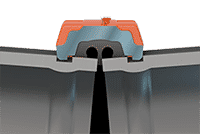
- Flexible couplings
- During the tightening procedure, the pads must close before the coupling key touches the outer diameter (OD) of the pipe within the groove.
- Rigid couplings - Tongue & Recess
- An equal and within-tolerance torque setting must be applied in a tightening sequence to ensure joint integrity. Note: Some tongue-in-recess styles have NO torque requirement and MAY even have dog teeth on the coupling keys to assist in the achievement of rotational rigidity.
- Install the housings over the gasket with the tongue-and-recess features mated properly (tongue in recess)
- Verify the housings keys engage the grooves completely on both mating components.
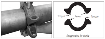
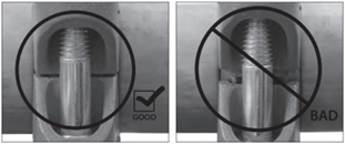
Figure 9 Installation of properly assembled joint of a tongue and recess rigid coupling.
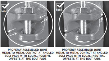
- Rigid couplings - Angle Pad
- Bolts must be gradually tightened on alternating sides allowing the gasket to move into the right place, until either an appropriate level of torque or pad-to-pad contact in the proper way is achieved.
- Rigid couplings – Sawtooth
- Gradually engage the sawtooth teeth by tightening the coupling bolts in a uniform and sequential manner.
- Confirm that the sawtooth teeth are securely engaged, providing a tight connection.
Both Tensioning Equipment
- Bolt Tensioning tools must be appropriate and not overpowered, review guidelines in coupling manufacturers data sheets.
- Nuts on couplers bolts must be tightened with the use of a torque wrench if the manual states it. A system to demonstrate that these have been met by marking the area or another quality assurance system must be used.
- Torque nuts and bolts to the values listed by the manufacturer with even gaps at the bolt pads if required by the installation instructions. If the application IS for Fire Protection the UL/FM approval will be affected if the proper procedure is not followed.
- Rattle guns/impact drivers must not be used on couplings that require a specific torque setting as it is impossible to check that the torque has been achieved.
- Certain models DO NOT require a specific torque setting so rattle guns or impact drivers may be used, although care must be taken not to over torque and damage threads. Always review the manufacturer's literature to establish how best to determine that the joint has been correctly installed. Some models require ONLY visual verification.
Supports and Installation
- Pipe ends must be clean and free from indentations, projections (including internal welds), and roll marks in the area from pipe end to groove for proper gasket sealing.
- Pipe support spacing and supports must be:
- Detailed by the designer taking into consideration any manufacturer requirements
- Installed in accordance with the manufacturer’s instructions and design documentation
Training
- The grooved coupling manufacturer’s certified trainer must provide on-site training for the subcontractor’s field personnel in the use of grooving tools and installation of grooved joint products.