Plasterboard Service Shafts
Key considerations
- Compartmentation Plans - Fire & Smoke
- Fire Resistance Level (FRL)
- Element Material FRL (i.e. wall, floor, ceiling)
- Service Material FRL (i.e. penetrating a compartment, FRL)
- Fire/smoke stopping system (as per MPX schedule)
- Sequencing of riser shaft construction or fire rated access panels may be required to complete correct installation of passive fire penetration systems and allow access to both sides of the wall.
- Just like any other fire wall, service penetrations in riser walls must be fire tested in the identical wall type to be suitable for use.
- Shaft Systems incorporating access panels, fire dampers, plumbing penetrations and the like, must be detailed to ensure both their fire and structural integrity is maintained. Refer to the service manufacturer or seal supplier for certification of fire performance.
- It is important that the project structural engineer approve the type, size and maximum spacing of perimeter fasteners to meet the design load requirements. Track fasteners shall be capable of withstanding a minimum of 0.86kN single shear and 0.89kN bearing force.
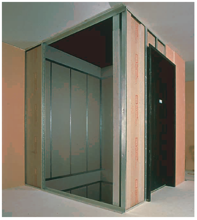
What are plasterboard riser shaft systems?
Plasterboard risers systems (ie. CSR Shaftwall, Boral Shaftliner, Knauf Shaftwall) are non-loadbearing fire resistance wall assemblies designed to encase lift shafts, stairwells and service risers in low and high rise construction.
Why use plasterboard riser shaft systems?
Plasterboard risers systems can be constructed from one side unlike many other fire rated wall systems that require access to both sides and is cost-effective. However, access is required to the inside of the riser to complete passive fire penetration systems. Fire rated access panels (such as FyreSHIELD) should be specified to allow access, otherwise the wall construction must be sequenced to allow access to install fire sealants/collars etc
Framing and Sheeting
Framing and sheeting must be:
- Installed as per the sequence recommended by the manufacturer. Refer example.
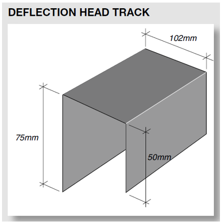
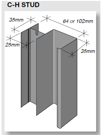
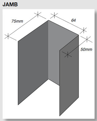
- Constructed with correct framing components. Refer Figure
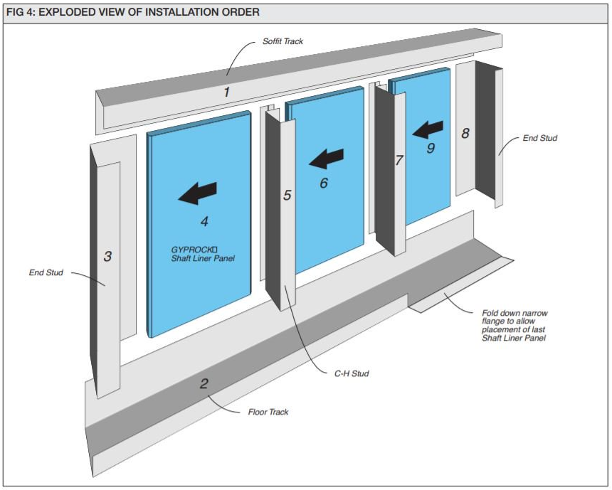
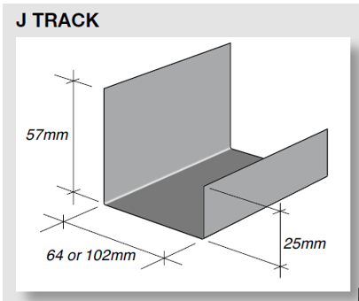

Framing
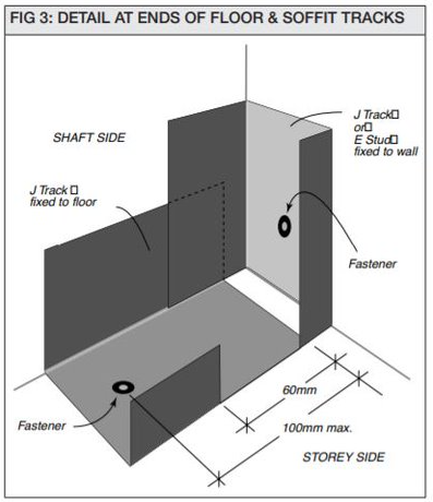
- Cut both the floor and soffit J tracks 20mm shorter than the actual length of the wall.
- Cut the narrow flange off both ends of the floor and soffit J tracks for a distance of 60mm maximum. Refer to Figure
- Accurately align the floor and soffit tracks according to the wall layout. Position the tracks with the narrow flange facing the storey side.
- Secure the floor and soffit tracks with fasteners at 100mm maximum from ends and at 600mm maximum centres.
- Cut the end stud 20mm shorter than the wall height. Position the stud with the 25mm face to the storey side.
- Fix the end stud to the wall with fasteners at 100mm maximum from the ends and at 600mm maximum centres.
- With steel frame construction, tracks and studs should be attached to steel columns and beams before the structural members are independently fire rated.
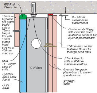
- C-H studs should be cut 13mm shorter than the wall height to allow a gap at the top of the studs.
Sheeting - Double Layer
Riser shaft walls must be:
- Fixed in accordance with the manufacturer's details (see example of CSR Shaftwall installation specifications).
Sheeting - Single Layer
Fix single layer systems as per the details for the second layer of double layer systems.
Head Details
Riser shaft head details must:
- Have J tracks fixed to soffit and 600mm max centres.
- Have studs 15-20mm clear of soffit.
- Be fixed in accordance with the manufacturer's details (see example of CSR Shaftwall installation specifications).
- Not have services penetrate through the head of the wall, unless tested and approved specifically in this configuration (eg Trafalgar FyreBOX Slab Mounted penetration systems).
Base Details
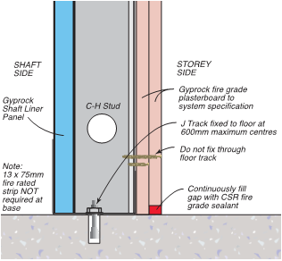
Riser shaft base details must be:
- Fixed in accordance with the manufacturer's details (see example of CSR Shaftwall installation specifications).
Wall Junctions
Junctions with Masonry Walls
Riser shaft walls junctions with masonry must be:
- Fixed in accordance with the manufacturer's details (see example of CSR Shaftwall installation options).
Inside and Outside Corner Details
Riser shaft walls inside and outside corners details must be:
- Fixed in accordance with the manufacturer's details (see example of CSR Shaftwall installation options).
Junctions with Stud Walls
Riser shaft walls injunctions with stud walls must be:
- Fixed in accordance with the manufacturer's details (see example of CSR Shaftwall installation options).

Click on the image for an enlarged view

Click on the image for an enlarged view

Click on the image for an enlarged view

Click on the image for an enlarged view
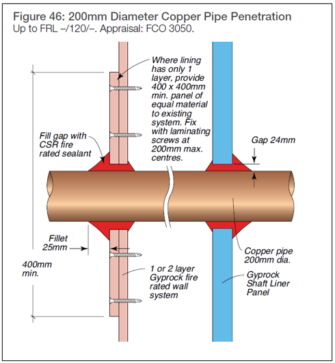
Penetrations
General
- Small penetrations can be done but must be strictly in accordance with the the evidence of suitability.(i.e. a fire test or assessment report).
- Access is required on both sides of the wall for the vast majority of riser shaft walls (eg even wall collar products require fire sealant applied on the rear face of the wall). Fire rated access panels (eg Trafalgar FyreSHIELD) can be fitted to allow access up to 600x600mm in size, whilst maintaining the wall FRL.

Click on the image for an enlarged view
Document Control
June 2024 – General updates regarding sequencing and penetrations