General
Fire Resistance
Fire Resistance is contained in Part C of BCA 2022. This Part focuses on minimising risk of illness, injury or loss of life due to fire in a building including during evacuation, reducing fire spread within and between buildings and minimising risk to the public and occupants of nearby buildings when a fire occurs.
The Objective of this Part C1, C2, C3 and C4 is to—
safeguard people from illness or injury due to a fire in a building; and
- (a) safeguard occupants from illness or injury while evacuating a building during a fire; and
- (b) facilitate the activities of emergency services personnel; and
- (c) avoid the spread of fire between buildings; and
- (d) protect other property from physical damage caused by structural failure of a building as a result of fire.
Part C2 introduces the concept of “Fire Resistance Level” amongst other matters like fire resistance, non-combustibility, etc.
Fire Resistance Level (FRL)
What is Fire Resistance Level (FRL)?
Fire Resistance Level (FRL) is defined in the Building Code of Australia (BCA)
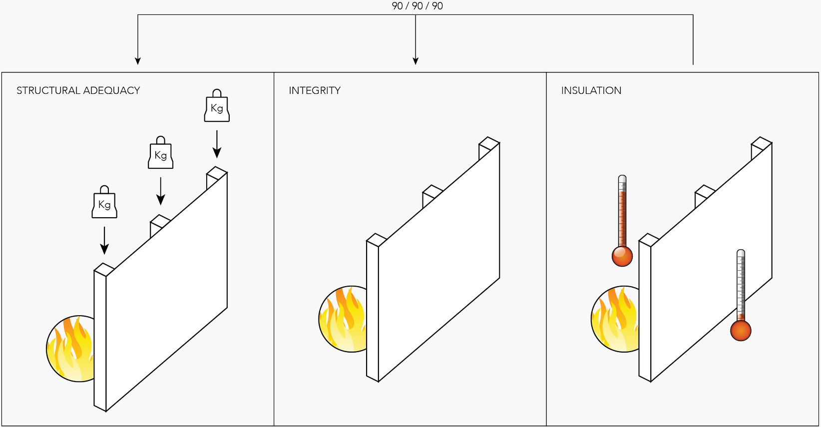
The grading periods in minutes determined in accordance with Specifications 1 and 2, for the following criteria—
- (a)structural adequacy; and
- (b)integrity; and
- (c) insulation,
and expressed in that order.
FRL values are determined by the standard fire test AS1530.4-2014, “Methods for fire tests on building materials, components and structures, Part 4: Fire-resistance tests for elements of construction”. The test results are stated in terms of whole minutes from the start of the test until a failure occurs in any of the three criteria and rounded down to the nearest 30 minutes.
A wall with a FRL of 90/90/90 means that the wall must maintain structural adequacy for 90 minutes, integrity for 90 minutes and insulation for 90 minutes.
Whenever an element of a building does not require an FRL, the non-required FRL is always expressed as a “-“; not a “0”, not as N/A, not by leaving the space blank. An example of this is a structural element such a steel column. It may only require structural adequacy. This then will be expressed as “120/-/-“.
Note that ‘resistance to fire’ (FRL’s and AS1530.4) are not to be confused with reaction to fire (‘AS1530.1, combustibility testing and AS1530.3).
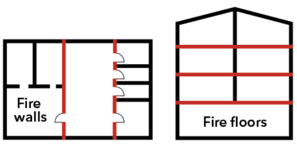
Compartmentation
What is Compartmentation?
Fire compartmentation is a crucial element of ‘passive fire protection’ and is achieved by dividing the building or part, into smaller areas. This is done through the use of fire-resistant construction, principally walls and floors. Within these may be found: -
- Doors, and
- Services that penetrate through these elements (service penetrations).
All penetrating items must maintain the integrity of the member penetrated.
Why do we do it?
- Life fire safety for the occupants of the building
- Prevents the spread of fire, smoke and toxic gases
- Subdivides buildings into manageable areas of risk
- Provides adequate means of escape enabling time for the occupants to evacuate the premises safely.
- Divide the building into safe havens for progressive evacuations,
- Allows for intervention by first responders, and
- To minimise loss.
Who is responsible to develop?
- Compartmentation plans are required to be developed by the architect and may require input from the Fire Safety Engineer.
How is it constructed?
The responsible MPX team member in each instance must:
- Ascertain the Fire Resistance Level (FRL),
- Review Subcontractor Sample submissions to confirm they can achieve the required FRL,
- Read the manufacturer’s installation instructions and evidence of suitability,
- Understand wall material type (i.e. Plasterboard, Hebel, Speedpanel, shaft wall, blockwork.)
- Review coordinated service penetration elevations,
- Coordinate service penetrations,
- Ensure installation of the fire stopping system is in accordance with the manufacturer’s installation instructions and evidence of suitability,
Resistance to the Incipient Spread of Fire (RISF)
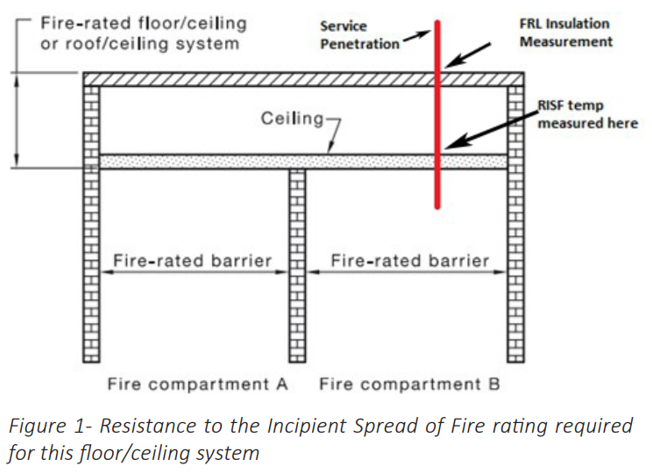
Resistance to the incipient spread of fire refers to the ability of a ceiling to prevent the spread of fire and thermally insulate the space between the ceiling and the roof or floor above. “Resistance to the incipient spread of fire” is superior to “fire-resistance” because it requires a higher standard of heat insulation.
Resistance to the incipient spread of fire: In relation to a ceiling membrane, means the ability of the membrane to insulate the space between the ceiling and roof, or ceiling and floor above, so as to limit the temperature rise of materials in this space to a level which will not permit the rapid and general spread of fire throughout the space.
The building code requires building designers to take into account the risk of fire spread within the cavity that is formed above a fire rated ceiling. This is a matter that is limited in use.
It is used: -
- To separate different types of construction where they occur within the same building in Type B and Type C construction.
- In Type A construction for a ceiling directly below a roof.
- For columns protected with light weight construction.
The RISF is determined as per AS1530.4 section 4 and introduces a second insulation (heat rise) criteria within the ceiling cavity to determine how well the ceiling membrane can prevent the spread of fire through the ceiling cavity. Failure is deemed to have occurred when the temperature above the ceiling exceeds 250 degrees Celsius.
The BCA requires 60 minutes of RISF ratings for all:
- Fire rated floor/ceiling systems (eg. plasterboard ceilings),
- Service penetrations, downlight covers, sprinkler head penetrations in fire rated floor/ceiling systems,
- Access hatches in fire rated floor/ceiling systems.
Any of the above building elements that do not have an RISF rating will not comply with the building code.
For example, a fire rated plasterboard ceiling with multiple layers of fire rated plasterboard suspended underneath a concrete floor must achieve an FRL of -/120/120 as well as an RISF rating for 60 minutes. Any service penetration in this ceiling must also achieve -/120/120 as well as an RISF rating for 60 minutes.
Compliance of service penetrations in fire rated barriers
Openings for the passage of a building service (electrical/plumbing/mechanical/ventilation/air-conditioning etc) must maintain the FRL of the wall, floor or ceiling that the service passes through.
For any service penetration to be compliant with the Deemed to Satisfy pathways of the BCABCA, the passive fire material must:
- Be identical with the tested prototype,
- Have been tested to AS1530.4-2014 sections 9 Air ducts, 10 Service penetrations and control joints and 11 Fire and air transfer grille assemblies in ducts.
- The testing lab must be an independent accredited laboratory that is recognised under NATA or mutually recognised scheme.
- Have been tested with the same pipe/cable/duct that is intended to be installed on site.
- Have been tested with the same wall, floor or ceiling type that is intended to be installed on site,
- Have achieved the required FRL with respect to Integrity & Insulation to match the fire barrier.
- If it is a penetration in a fire rated ceiling, also achieve at least 60 minutes of Resistance to the Incipient Spread of Fire (RISF).
Minor variations from the tested prototype are only permitted in the following ways:
- In accordance with the ‘Permissible variations’ from AS1530.4 sections 9.9, 10.12 and 11.9
- Be in the form of a written report from an accredited test laboratory in accordance with AS4072.1-2005 where all variations are fully justified and minor in nature. These are sometimes referred to as “assessment reports” or
- In the form of a Fire Engineering Report (FER) written by a Fire Engineer,
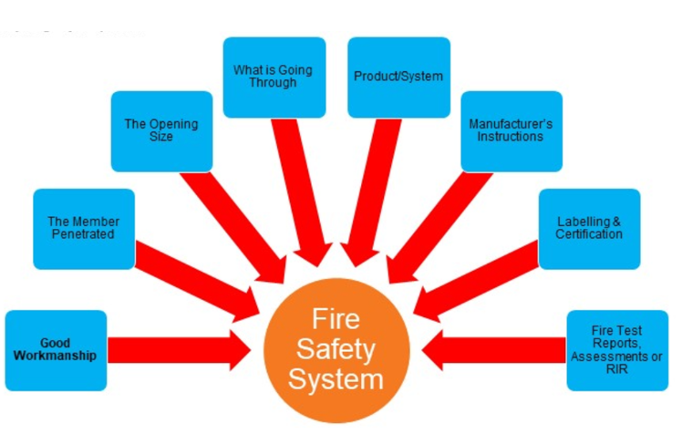
When evaluating or selecting fire rated penetration systems, the entire system must be reviewed:
Separation of Service Penetrations
Each penetration and its distance to others should be evaluated using the following points:
- In lieu of an installation standard, 200mm separation is a conservative separation design based on AS1530.4 fire test requirements
- AS4072.1-2005 does allow the separation distance between separate service penetrations to be reduced down to as close as 40mm apart, via a valid/current fire assessment report from an accredited test laboratory. This only applies to specific penetration systems that are assessed in the report.
- Services must not be installed at or through the deflection heads of any wall type, unless the penetration system has been evaluated in a full-scale fire test to AS1530.4-2014
- AS1682.2 requires fire dampers to be installed 200mm away from any other service, and 75mm away from head of any wall
- Trade specific codes and standards also require certain separation to prevent cross contamination or interference.
- Penetrations installed in load bearing elements must be designed in accordance with relevant design standards (AS3600/3700 etc) to ensure the presence of these penetrations are acceptable and may require additional detailing such as lintels.
Where spacing requirements for building service penetrations cannot comply with the above, select a penetration system that has been tested specifically for use with multiple services box type style system penetration, where services can be combined.
Process
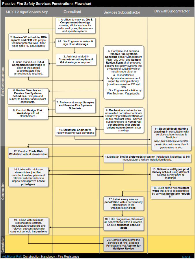
- Management of the passive fire process must be in accordance with "Passive Fire Safety Systems" flow chart below:
Document Control
June 2024 – General updates relating to the definition of fire resistance and inclusion of the requirements for resistance to the Incipient Spread of Fire (RISF) and compliance of service penetrations in fire rated barriers