Hebel Walls
Key considerations
- Compartmentation Plans - Fire & Smoke
- Fire Resistance Level (FRL)
- Element Material FRL (i.e. wall, floor, ceiling)
- Service Material FRL (i.e. penetrating a compartment, FRL)
- Fire/smoke stopping system (as per MPX schedule)
- Additional steel framing required for large penetrations.
What is the Hebel?
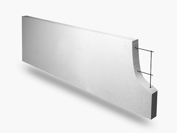
Hebel is autoclaved aerated concrete (AAC), manufactured from sand, lime and cement to which a gas-forming agent is added. The liberated gas expands the mixture, forming extremely small, finely dispersed air pockets, resulting in lightweight aerated concrete.
Note that there are now other brands of AAC walls available in the market. Fire testing from one brand is NOT compatible with another. Each different brand will have separate (and often different) fire test approvals, including testing of service penetration systems.
Hebel wall systems contain steel reinforcement with an anti-corrosion protection layer for added strength and durability.
Why use Hebel?
Hebel provides:
- Lighter loads on the structure compared to traditional masonry products.
- Reduced structural sizes and speed of installation with subsequent cost savings compared to traditional masonry construction.
- Thermal resistance performance and effective sound transmission barriers between external and internal environments of the buildings.
- Fire rating properties with fire resistance levels (FRL).
Note: Hebel is best situated to be installed as intertenancy and bounding walls where they are not penetrated by services.
Framing
General
Hebel walls must:
- Be installed as per Hebel’s Installation Guide, which includes the requirements as noted in the Figure.
- Have screws with a minimum 50mm from edges or ends of Hebel panels.
- Have screws embedded 10 to 15mm below the surface.
- Use Hebel Adhesive or Hebel Patch Compound to cover the screw.
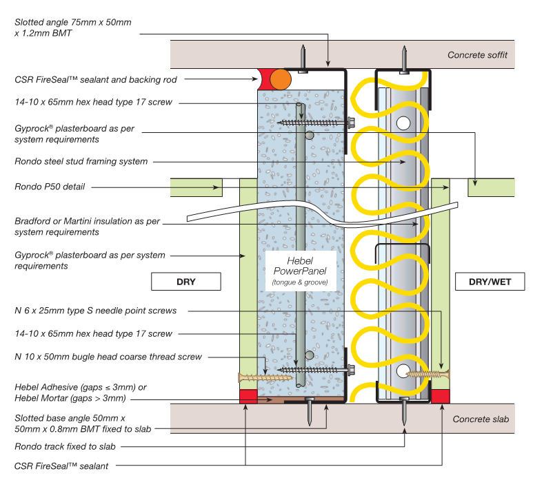
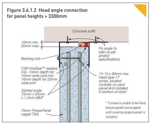
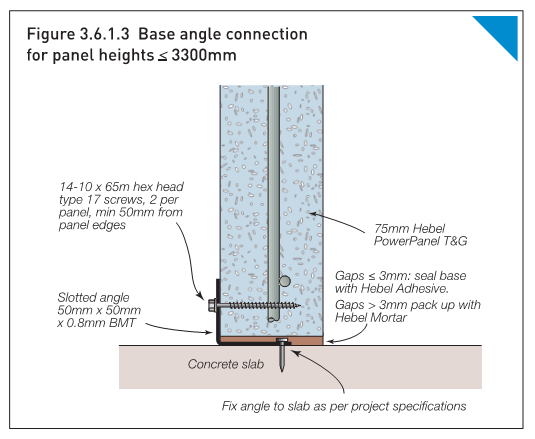
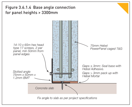
Head and Base Angles
- Fix slotted angles and base angles at 600mm maximum centres and maximum 100mm from ends to the concrete support structure must be installed.
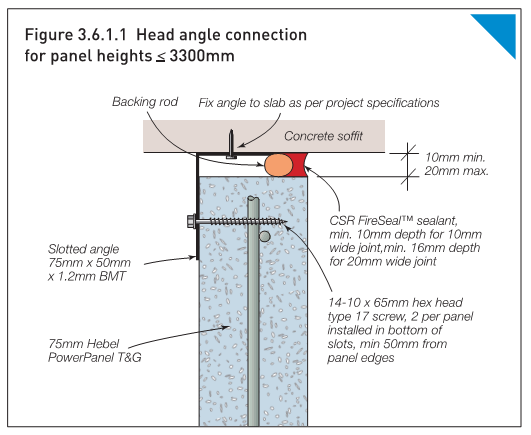
- A minimum of 10mm and a maximum 20mm gap at the head of the panel must be maintained.
Head track angle must be:
- 75mm x 50mm with 1.2mm BMT (<3.3m in height)
- 2x75mm x 50mm with 1.2mm BMT (>3.3m in height)
Base angle must be:
- 50mm x 50mm with a 0.8mm BMT (<3.3m in height)
- 75mm x 50mm with a 1.2mm BMT (>3.3m in height)
Panels
FRL and Heights
- Refer to the table below a guide to the FRL that may be achieved for the nominated wall heights.
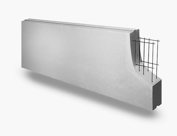
- Panels over 3300 mm must be made with caged mesh.
Table 1: Hebel PowerPanel tongue & groove 75mm standard and made-to-length sizes, CSR Hebel: High Rise Apartments Student Accommodation Hotels Commercial Design & Installation Guide, HELIT117 Aug 16
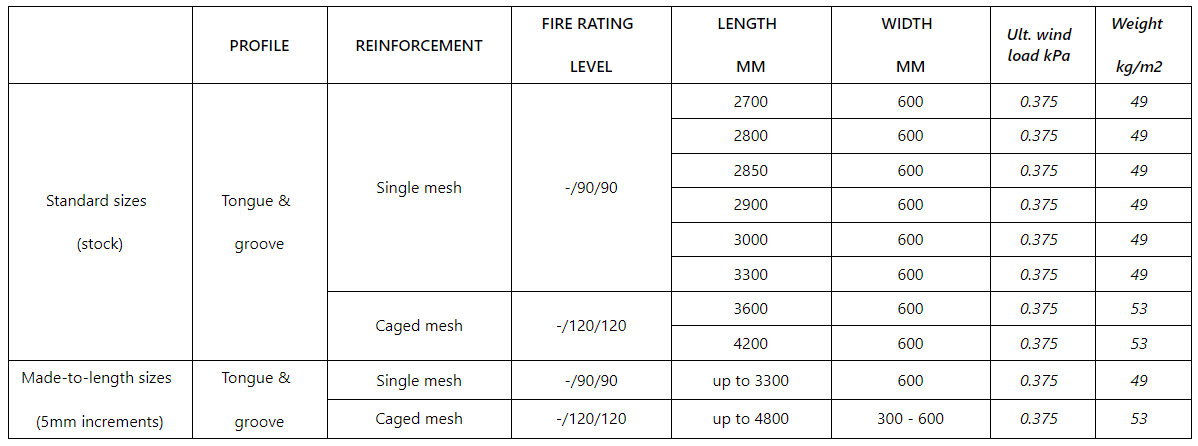
Notes: Average panel weight calculated 30% moisture content ^Panels over 3300mm use caged mesh.
Vertical Junction Details
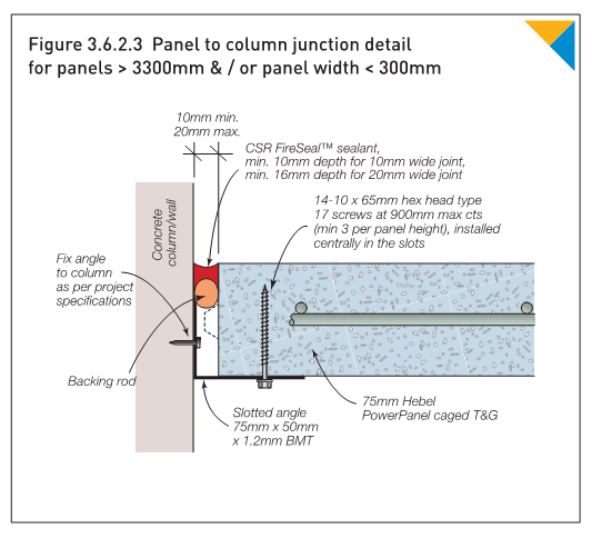
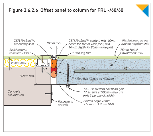
Panel Abutting Concrete
Panel abutting to concrete must:
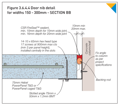
- Have a 10 -20mm gap when abutting other materials (i.e. concrete columns).
- Installed as per Figure.
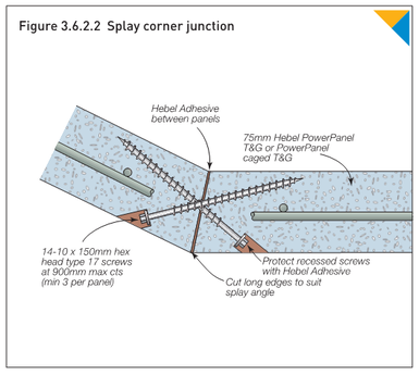
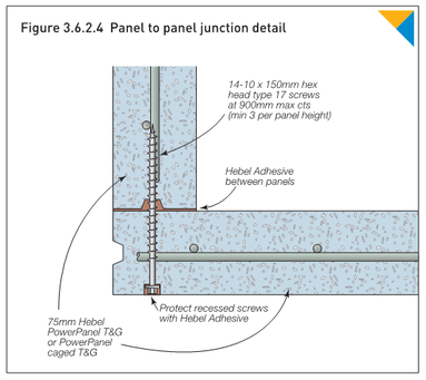
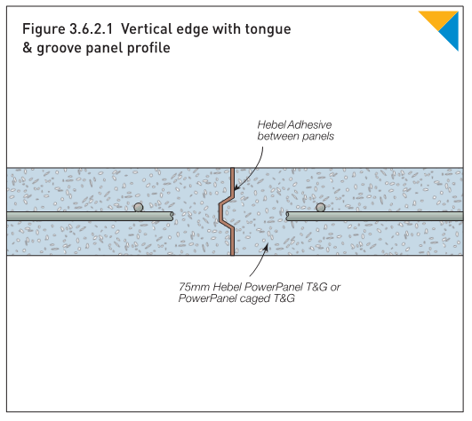
Panel Junctions
Panel junctions must:
- Have 14-10 x 150mm hex head type 17 screws at maximum 900mm centres (min 3 per panel).
- Have adhesive applied between panels.
- Installed as per Figures.
Joints
Joints must:
- Have adhesive applied between panels.
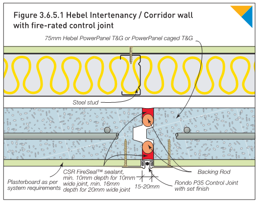
Control Joints
Control joints must be:
- Located at 6m centres.
- Have a slotted head and base track discontinuous at the control joint.
- Not have services penetrate through control joints.
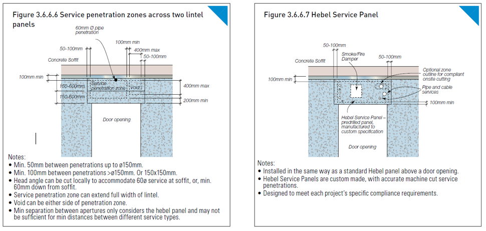
Penetrations
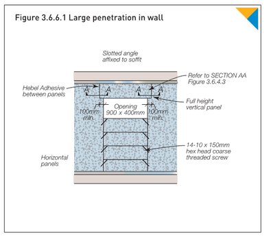
Panels (Structural Adequacy)
- Never more than one-third of a panel’s width can be cut, N.B. maximum 200mm for a 600mm panel.
- Large openings must have:
- Lintel panels over large openings >600 mm wide (refer to Door Details for stitching screw details).
- Horizontal panels used below the opening.
- Must use Hebel Service Panels when penetrated by services
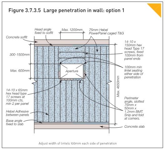
- Additional steel framing to brace the penetration, as approved for the specific service penetration system (eg Trafalgar FyreBOX approvals for penetrations wider than 400mm wide in report FC10266)
- Cut ends of reinforcement must be painted with Hebel corrosion protection paint.
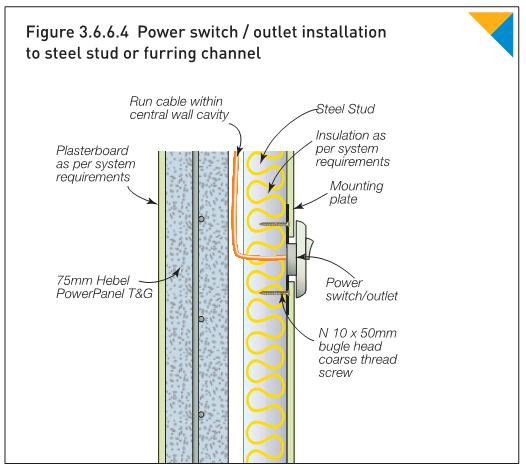
Cable Penetrations
Single Cable
Single cables must be:
- Installed in accordance with the evidence of suitability which should:
- Be installed in accordance with the manufacturers installation details.
- Have a separation between any other penetration.
- Be sealed.
- Example: Trafalgar FyreFLEX Sealant is approved under fire assessment report FCO1579 and allows for various power/data cable constructions. Each penetration sealed with FyreFLEX is approved to be as close as 40mm apart, although best practice is to allow more separation where practical. Larger cables may also require additional thermal wrap, to maintain the insulation criteria of the FRL.
Bundled Cables
Bundled cables must be:
- Installed in accordance with the evidence of suitability which should:
- Have a separation between any other penetration.
- Be sealed.
- Installed with the maximum size of bundled cables considered.
- Example: Trafalgar FyreFLEX Sealant is approved under fire assessment report FCO1579 and allows for various power/data cable constructions with bundles up to 4-5 x depending on the cables. Each penetration sealed with FyreFLEX is approved to be as close as 40 mm apart, although best practice is to allow more separation where practical.
- Larger cable bundles may increase the heat rise through the wall and usually will require additional wrapping materials along with the sealant as a ‘full system’.
Cables on Trays
Cable trays must be:
- Installed in accordance with the evidence of suitability which should:
- Have hangers installed 150mm maximum from either side of the wall.
- Be wrapped either side to maintain insulation criteria.
- Example: Trafalgar FyreFLEX Sealant is approved under fire assessment report FCO1579 and allows for various power/data cable constructions with bundles up to 4-5x depending on the cables. Each penetration sealed with FyreFLEX is approved to be as close as 40 mm apart, although best practice is to allow more separation where practical.
Conduits
Conduits must be:
- Installed in accordance with the evidence of suitability which should:
- Have either an intumescent sealant or fire collar fixed with steel fasteners.
- Smoke sealed internally when passing through 2 compartments or more.
- Have a separation between any other penetration.
Note: size limitations may apply to some fire stopping systems:
- Promat Conduit Collar = Max. 32mm conduit.
- Trafalgar FyreCOLLAR’s are approved under report FC11190 for PVC conduits up to a max. 50 mm when installed on both sides of the wall.
- Trafalgar FyrePEX HP sealant is approved under FAR4849 to seal PVC conduits up to 40 mm in hebel walls, applied from one side of the wall only (however intumescent sealants do have restrictions on the penetration’s aperture size)
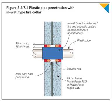
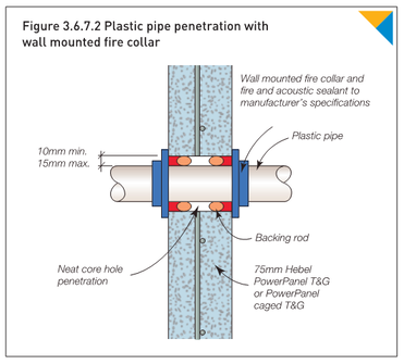
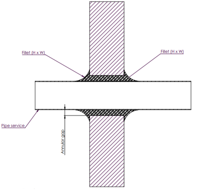
Hydraulic Pipework
Combustible i.e. PVC, hdpe, p-e-x
Combustible pipework must be:
- Installed in accordance with the evidence of suitability which should:
- Be installed with a retrofit collar or through collar (in wall-type) as per evidence of suitability.
- Have a 10-15mm annular gap.
- Be sealed in accordance with the Figures or as as per evidence of suitability.
- Have a separation between any other penetration.
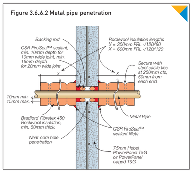
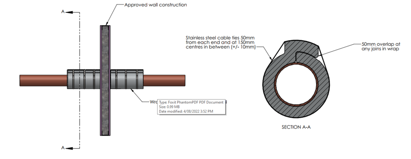
Hydraulic Pipework
Non-Combustible i.e. Copper
Non-combustible pipework must be:
- Installed in accordance with the evidence of suitability which should:
- Sealed at the wall with a tested fire sealant to maintain the FRL integrity criteria.
- Be wrapped with insulation from the surface of the wall to maintain FRL insulation criteria.
- Be wrapped with insulation though the wall for chilled or hot water pipe to maintain insulation criteria.
- Be sealed in accordance with the Figures.
- Have a separation between any other penetration.
- Example: FyreFLEX and TWrap is approved as a combined system under report FCO1579 to maintain the FRL of the hebel wall and allow for metal pipes to penetrate the wall. Larger pipes require larger amounts of wrap due to increase levels of heat transfer.
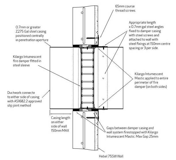
Fire Dampers
Fire dampers must be:
- Installed in accordance with the evidence of suitability which should:
- Have a separation between any other penetration
- Installed as per section Fire Dampers and Figure.
Doors
Door Nib Detail
- Door nibs must never be smaller than 100 mm or as otherwise required to ensure FR doors open past 90 degrees and do not diminish the width of the required exit.
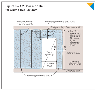
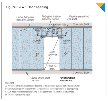
Door Opening
- Openings must have a lintel over with a max depth of 700mm and max span of 1200mm
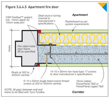
- Door frames must be:
- Securely fixed using Type 17 screws at a 300mm centres, or as otherwise tested.
- Filled top and sides as required by the fire test report.
- Cut ends of reinforcement must be painted with Hebel corrosion protection paint.
Document Control
June 2024 – General updates relating to cables, cable trays and conduits