Plasterboard Walls
Key considerations
- Compartmentation Plans - Fire & Smoke
- Fire Resistance Level (FRL)
- Element Material FRL (i.e. wall, floor, ceiling)
- Service Material FRL (i.e. penetrating a compartment, FRL)
- Fire/smoke stopping system (as per MPX schedule)
Framing
Design
Steel stud manufacturer to produce design and workshop drawings including but not limited to: -
- noggings for attachment of grab rails,
- coat hooks,
- door stops,
- cupboards,
- bump rails, etc,
- seismic detailing, and
- framing for door and service penetration openings.
Expected long term creep deflection with Structural Engineer must be confirmed
Steel Stud Framing
- Wall studs must be selected based on the manufacturer's/designers workshop drawings which are based on wall height and number of lining boards.
- Base metal thickness (BMT) and stud centres must be in accordance with workshop drawing.
- Ensure framing centres and noggings are installed as detailed in the workshop drawings.
- Studs are to be cut 20 mm short of the slab soffit or as otherwise detailed in the workshop drawings.
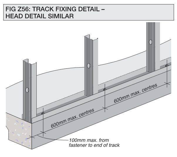
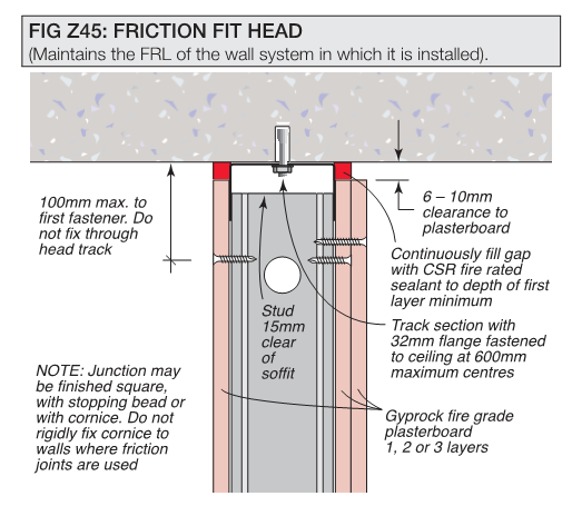
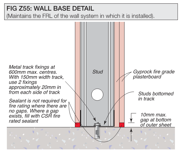
Wall Head/Base Details
Top and bottom tracks installed must have:
- Fasteners at a maximum 600mm centres but may be less depending on project requirements and with the first fastener no greater than 100mm from the end of the track, and on all placed on the centreline of the track.
- Service penetrations should never penetrate the head track of a wall unless they have been tested in full scale AS1530.4-2014 to show compatibility with the deflection head (E.g. Trafalgar FyreBOX Slab Mount).
Sheeting
- Plasterboard and fasteners must be as per approved samples.
- Sheets must be screw fixed to framing using zinc plated bugle head screws.
- Refer to the manufacturer’s specific requirements for screw placement and frequency noting that:
- First layer sheets are screwed at a greater spacing than following layers.
- Outer layers are generally screwed at 200 mm centres at:
- Butt joints and
- 300 mm in the body of the sheets.
- No closer than 15 mm to the sheet edge.
- Firewalls must be smoke sealed.
- Fasteners
must be installed in accordance with the manufacturer’s details (refer to the table and figures below of the CSR screws for fixing plasterboard).
Table 1: Example of CSR Screws for fixing plasterboard to steel (Note: other manufacturer details may be different)
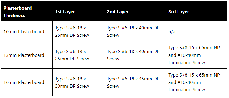

Click on the image for an enlarged version
Corners and Intersections
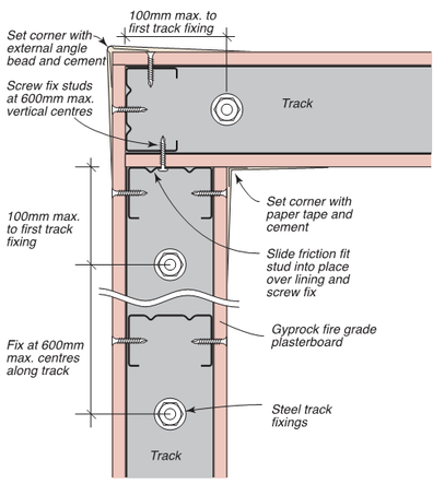
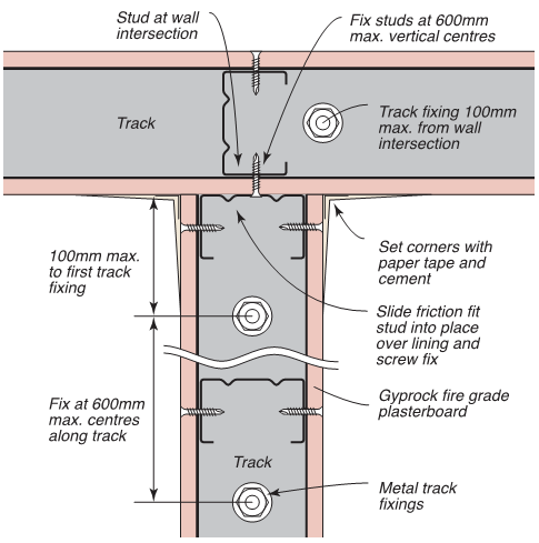
Internal corners must or as otherwise specified by the manufacturer:
- Be set with paper tape and 2 coats of base coat,
- Installed as Figures below.
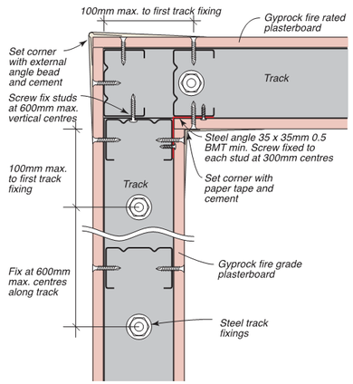
External corners must or as otherwise specified by the manufacturer:
- Be set with an setting bead and 2 coats of base coat,
- Installed as Figures below.


Click on the image for an enlarged version
Sheet Joints
- All joints in the outer layer of all systems must be set with paper tape and 2 coats of the base coat as a minimum and filled flush.
- Butt joints must be:
- Backed by either a stud or noggin in all first layers.
- Staggered by 600 mm minimum in adjacent sheets and on opposite sides of the wall.
- Fixed at 150- or 200-mm maximum centres.
- Recess joints must be offset on opposite sides of the wall by one stud.
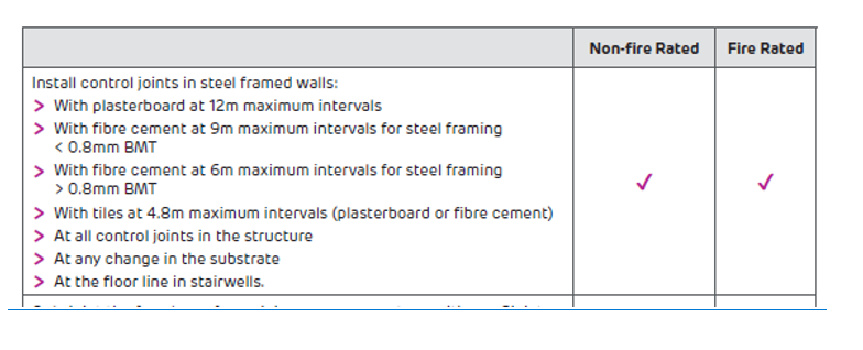
Control Joints
Control Joints
What are control joints?
- Control joints are a discontinuity in the sheeting and framing to allow for movement in the building structure.
Why are control joints used?
- To prevent the deformation and damage to internal linings and partitions that may be caused by movement and stresses created by fluctuations in temperature and humidity and long term creep deflection.
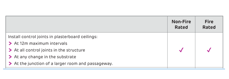
- To relieve stresses of expansion and contraction of internal plasterboard ceilings and walls:
- Wherever the ceiling or wall abuts structure or other wall types.
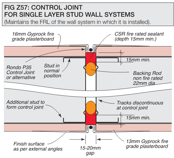
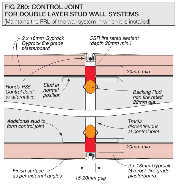
Before installation of a control joint:
- Top and bottom tracks cannot be continuous and must mirror the gaps in the studs.
- Studs must be 15 mm – 20 mm apart, orientated back-to-back.
- Sheeting must also allow a 15 mm – 20 mm gap.
- A 22 mm diameter backing rod is inserted into the gap to ensure correct dimensions of the sealant
Install control joints:
Apply fire rated sealant to the joint as specified by the manufacturer.
Penetrations
General
Penetrations must be:
- Installed as per evidence of suitability,
- Tested in the same thickness plasterboard facing and stud width,
- Able to be installed with access to both sides of the wall (including shaft walls),
- Have services separated appropriately,
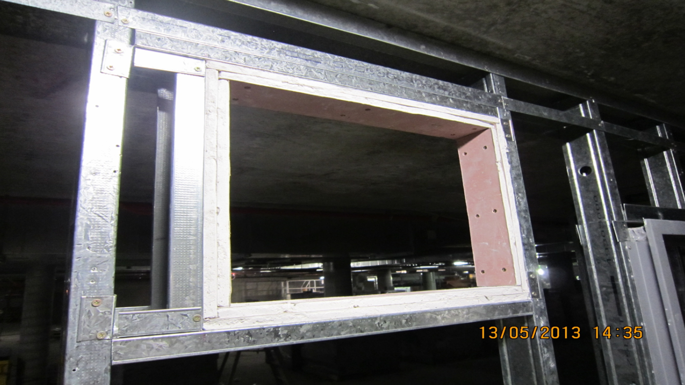
- Square or rectangular penetrations must be:
- Framed with stud and track to all four sides, and
- Lined with layers of plasterboard as per the wall layers fixed to the faces of the wall.
Smaller circular penetrations generally do not require additional stud framing, but should be confirmed with the passive fire manufacturers test reports, unless the stud has been cut.
Hydraulic Pipe
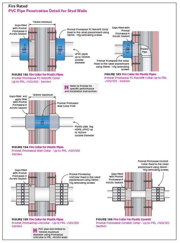
Combustible i.e. PVC
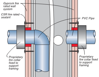
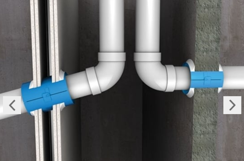
Combustible pipework must be:
- Installed in accordance with the evidence of suitability which should:
- Be installed with a retrofit collar or through collar as per evidence of suitability (Note: Through collars should not be used for wall greater than 128mm and still require access to both sides to apply sealants)
- Be sealed as per evidence of suitability (i.e. fire test report or regulatory information report, or assessment from the collar manufacturer)
- Be installed on both sides of the wall, using the approved steel screw fixings.
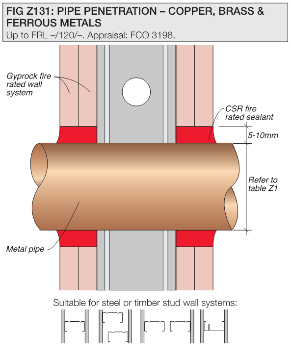
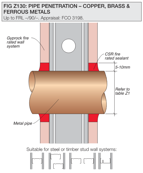
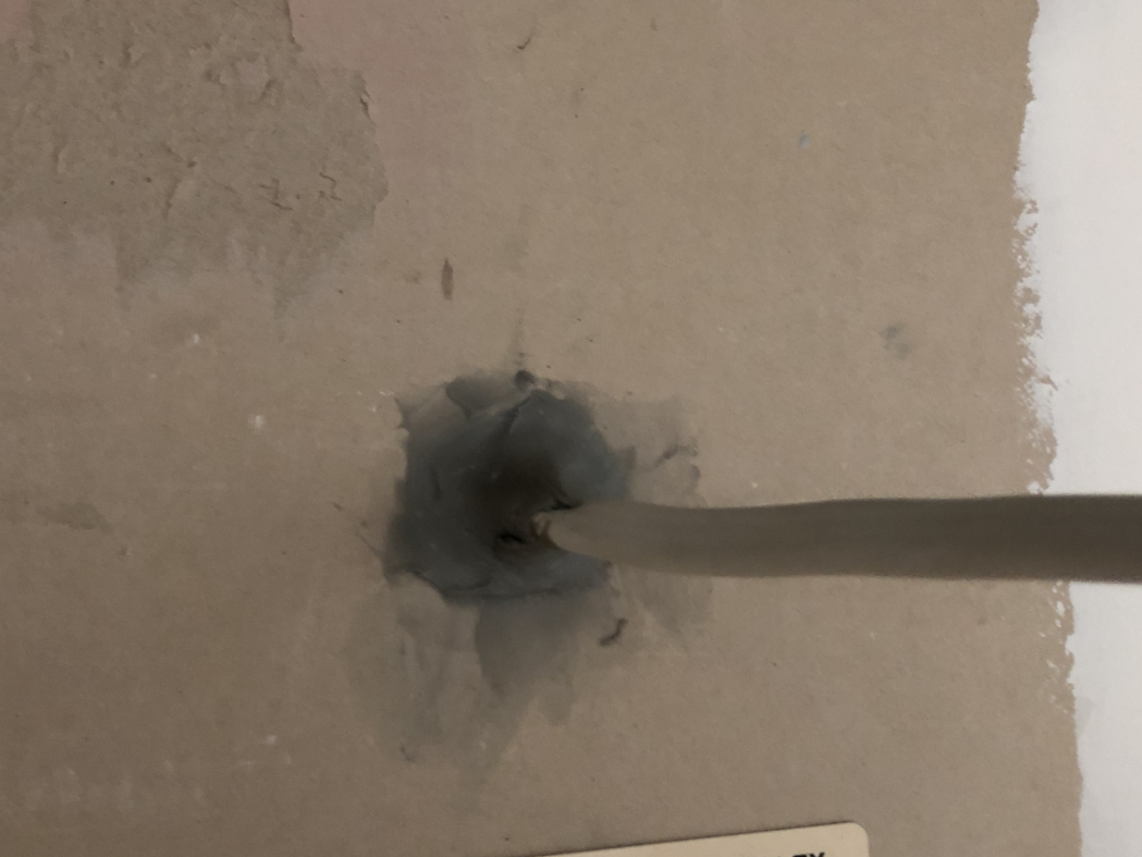
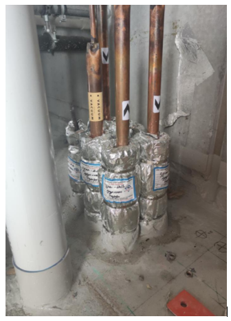
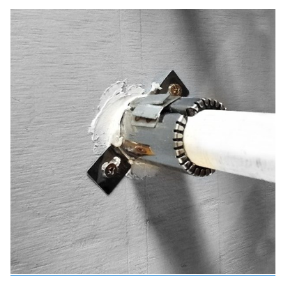
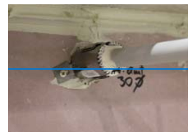
Non-Combustible pipes i.e. Copper, Brass & Ferrous Metal (does not apply to fuel pipes)
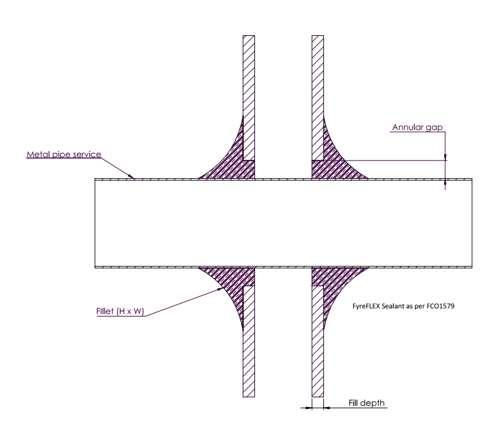
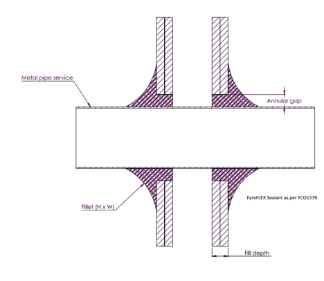
Non-combustible pipework must be installed as specified by BCA 2022, Section C, Part C4, & Specification 13, clause S13C3 and:
- Installed in accordance with the evidence of suitability and:
- Be sealed as per evidence of suitability (i.e. fire test report or regulatory information report, or assessment from the sealant manufacturer).
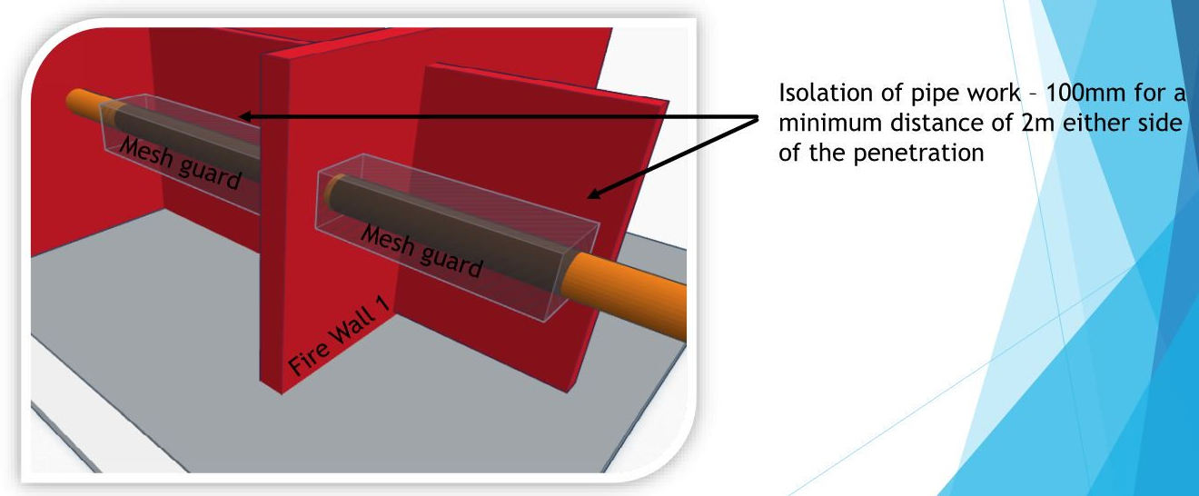
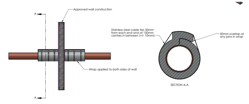
- Be wrapped with the tested thermal insulation material from the surface of the wall for a specified distance to maintain insulation criteria e.g. -/XXX/120. For correct wrap sizes and distance of the fire barrier, refer to fire test reports or regulatory information report or assessment.
- Be treated on both sides of the wall.
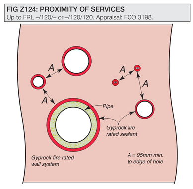
- Unless wrapped, be no closer than 100mm to any other service penetration (refer Figures below)
- Be sealed in accordance with the diagrams below .
- Have a min of 50mm separation from the edge of any other drilled penetration (i.e.. single, bundled cable or insulated penetration) or as specified.
- Have a min of 200mm separation from the edge of any other formed penetration or as specified.
- A pipe system comprised entirely of metal (excluding pipe seals or the like) must be wrapped but must not be lagged or enclosed in thermal insulation over the length of its penetration of a wall, floor or ceiling unless the lagging or thermal insulation fulfils the requirements of S13C7.

Cable Penetrations
Single Cable
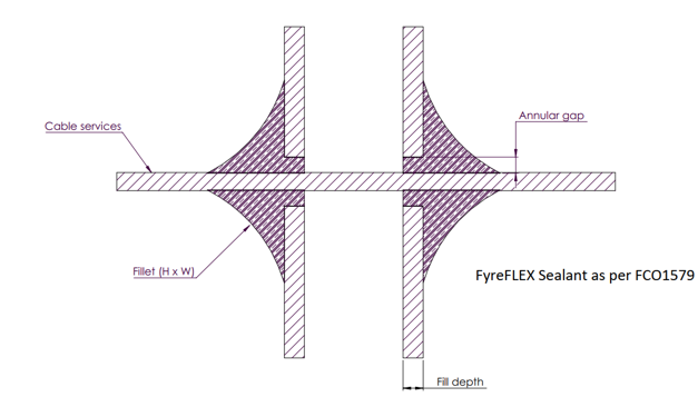
Wires and cables must be:
- Installed in accordance with BCA 2022, Section C, Part C, clause S13C5, and
- Installed identical with the evidence of suitability (i.e. fire test report or regulatory information report or assessment from the sealant manufacture) which should:
- Have a min of 50mm separation from the edge of any other drilled penetration (i.e.. single, bundled cable or insulated penetration) or as specified.
- Have a min of 200mm separation from the edge of any other formed penetration or as specified (eg. fire dampers)
- Be sealed with a sealant/mastic that has been tested to AS1530.4 for use with the specific wall type
- Be sealed on both sides of the wall
Bundled Cables
Bundled Cables must be:
- Installed in accordance with the evidence of suitability (i.e. fire test report or regulatory information report or assessment from the sealant manufacturer) which should:
- Have a min of 50mm separation from the edge of any other drilled penetration (i.e.. single, bundled cable or insulated penetration) or as specified.
- Have a min of 200mm separation from the edge of any other formed penetration or as specified (eg. fire dampers)
- Be sealed with a sealant/mastic that has been tested to AS1530.4 for use with the specific wall type
- Be installed within the maximum size of bundled cables that have been tested/approved in the specific wall type, otherwise cables must be split into separate bundles or a different fire stopping system should be used that is tested for use with large bundles (eg. Trafalgar FyreBOX or Trafalgar FyreBATT systems).
- Be sealed on both sides of the wall
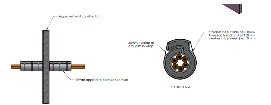
Larger cables and bundles will require additional wrapping to address the heat transfer (insulation criteria) using a thermal insulation wrap such as Trafalgar TWrap as shown in Figure below.
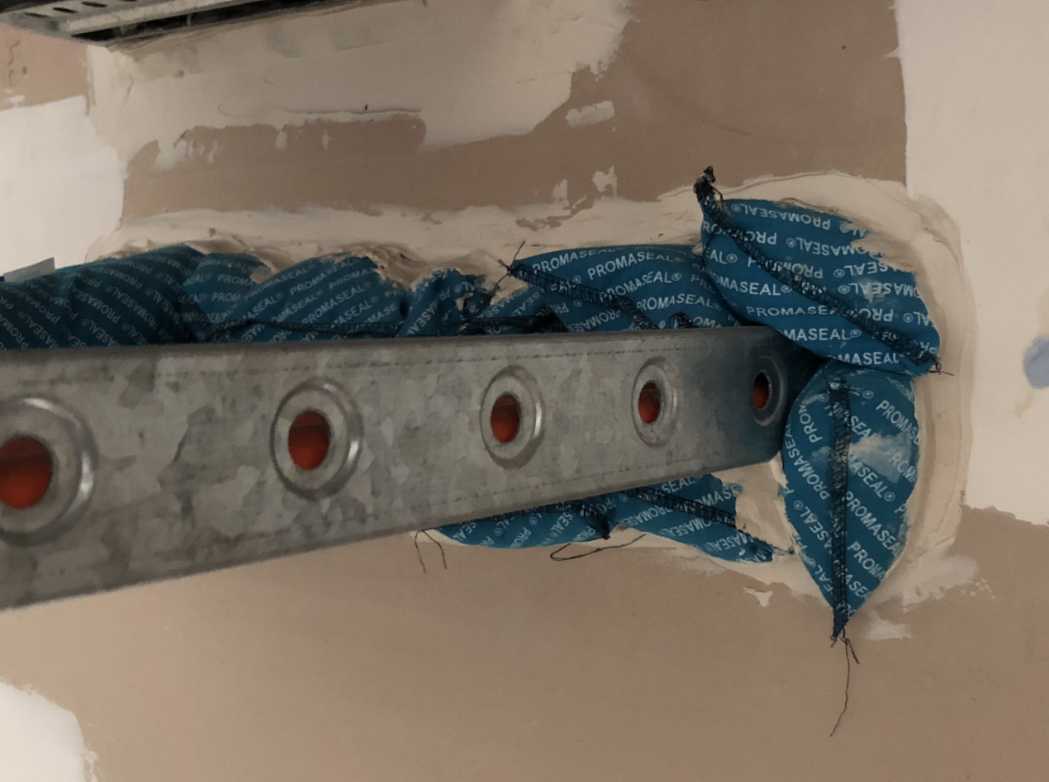
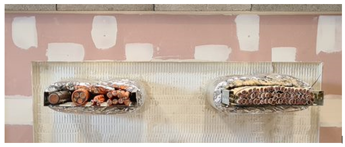
Cable Trays
Cable trays of any size must be:
- Installed in accordance with the evidence of suitability (i.e. fire test report or regulatory information report or assessment from the product manufacturer) which should:
- Be filled with batts, pillows, boards or FyreBOX’s as per diagrams below
- Apertures cut for service penetrations must be lined with stud/track on all 4x sides, and lined with strips of plasterboard (the same number of layers as on the face of the wall) to protect the wall cavity.
- Be wrapped either side to maintain insulation criteria
- Have a min of 50mm separation from the edge of any other drilled penetration (i.e.. single, bundled cable or insulated penetration) or as specified.
- Have a min of 200mm separation from the edge of any other formed penetration or as specified (eg. fire dampers).

Click on the image for an enlarged version

Click on the image for an enlarged version
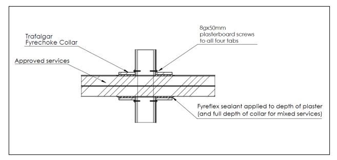
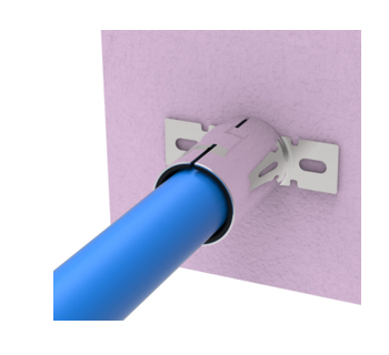
Conduits
Conduits must be:
- Installed in accordance with the evidence of suitability (i.e., fire test report or regulatory information report or assessment from the product manufacturer) which should:
- Have either an intumescent sealant or fire collar fixed with the correct steel fasteners as per the fire test approval report.
- Be smoke sealed internally when passing through 2 compartments or more.
- Have a min of 50mm separation from the edge of any other drilled penetration (i.e. single, bundled cable or insulated penetration) or as specified.
- Have a min of 200mm separation from the edge of any other formed penetration or as specified (eg. fire dampers).
- Note: size limitations may apply to some fire stopping systems:
- Promat Conduit Collar = Max. 32mm conduit.
- Trafalgar FyreCOLLAR Conduit Collars = Max. 40 mm conduit.
- Penetration size cut for conduit must be sized tight to suit, or an oversized penetration are required to close the opening.
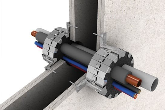
Figure 11 Trafalgar FyreCOLLAR Conduit
Fire Dampers
Fire dampers must be:
- Installed in accordance as detailed in AS1668.1:2015, The use of ventilation and air conditioning in buildings Fire and smoke control in buildings, and with the evidence of suitability which should:
- Have jamb or boxed studs and trimmers.
- Be lined with the same numbers of plasterboards layers as that used on the face of the wall.
- Have a min of 200mm separation from the edge of any other penetration.
- Be installed as per section Fire Dampers and figure below.

Click on the image for an enlarged version
Doors
Door frames must:
- Framed with a jamb or boxed studs
- Be securely fixed at 3400 centers
- Filled top and sides in accordance with the evidence of suitability
- Installed as per Section Fire Resistance Doorsets
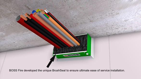
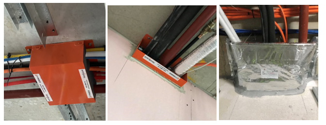
Multi-Services
Multi-services (cable trays, PEX and PEX-AL-PEX pipes, conduits, lagged and bare metal pipes etc) may be installed through one single penetration utilising the BOSS Fire® Transit Box or Trafalgar Fire FyreBOX range , and must:
- Be installed in accordance with the manufacturer’s installation details and fire test approvals.
- Be installed central to the wall studs (or additional framing may be required).
- Be installed before or after the walls have been erected.
- Maintain service separation within the multi services box to meet local trade code requirements (eg. power/comms 50mm apart).
- Have the minimum fill ratio requirements (not required for the Trafalgar FyreBOX).
- Have foam plugs installed on both sides of the wall (if specified by the manufacturer).
- Have a thermal insulation wrap where required depending on the metal services present.
Repairs
- Repairs to plasterboard fire walls are not recommended.
- If a sheet is damaged, or a service needs to be relocated, then the repair needs the same considerations as with any other penetration in a fire wall. It must be repaired to the requirements of a tested system.
- Note: appropriate details for plasterboard and shaft liner, can be found in the Gyprock Professional Solutions Guide – Repair Of Gyprock® Fire Rated Wall & Ceiling Linings, available by contacting DesignLINK.
- Consideration must be given to the running of temporary services through firewalls, and what stopping, or repair systems can be applied upon removal of any temporary services.
- Temporary services through fire barriers should be avoided where possible.
Document Control
June 2024 – General updates in relation to requirements for penetrations, pipework, cables, cable trays, conduits, multi services and repairs.